The bellow frame encoder/decoder works for simple AX.25 frames where only one destination and source address is used, each up to 6 characters long plus the SSID field. Both the PID and Control fields are also encoded/decoded. They can be input in either decimal or HEX format. The payload has to be in ASCII characters and with a maximum length of 255 characters. These fields are then used to generate the AX.25 frame first, shifting the address bytes and adding the end address bit to the last byte of the address field. The result is displayed in HEX format in the “AX.25 Frame” field.
The generated AX.25 frame is then encoded into the complete AX.25 HDLC frame, the bit order is inverted (LSBit), the FEC is calculated (16-bit CRC-CCITT) and added to the end of the frame, bit stuffing is done, start and end flags are added. The result is displayed in HEX format in the “HDLC Frame” field.
The frame generator updates in real-time and also works in reverse. Changing any field, including the “AX.25 Frame” or the “HDLC Frame” updates all the others, doing encoding and decoding accordingly. The JavaScript source code used can be downloaded bellow.
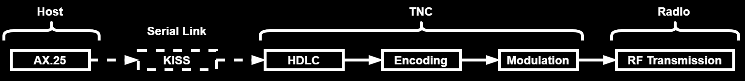
In a normal/standard communication that uses AX.25 frames, there are 4 protocol layers involved: AX.25, HDLC, encoding/scrambling and modulation. The first two layers are part of the data link layer (2nd in the OSI layers), with the AX.25 frame being a derivation/extension of the HDLC frame. The last two are part of the physical link layer (1st in the OSI layers). All four layers are explained in the following sections.
Due to how the use of AX.25 protocol in HAM Radio evolved, and digital communication in HAM Radio in general, there is often one additional communication protocol involved, the KISS protocol. This protocol is used to transmit AX.25 frames from a Host (PC) to a TNC over a asynchronous serial link. In that case, the Host assembles the AX.25 frame and the TNC implements the other 3 layers and connects to a HAM Radio, often over a audio link, for RF transmission. Bellow is a simple block diagram showing the different layers and their interconnections:
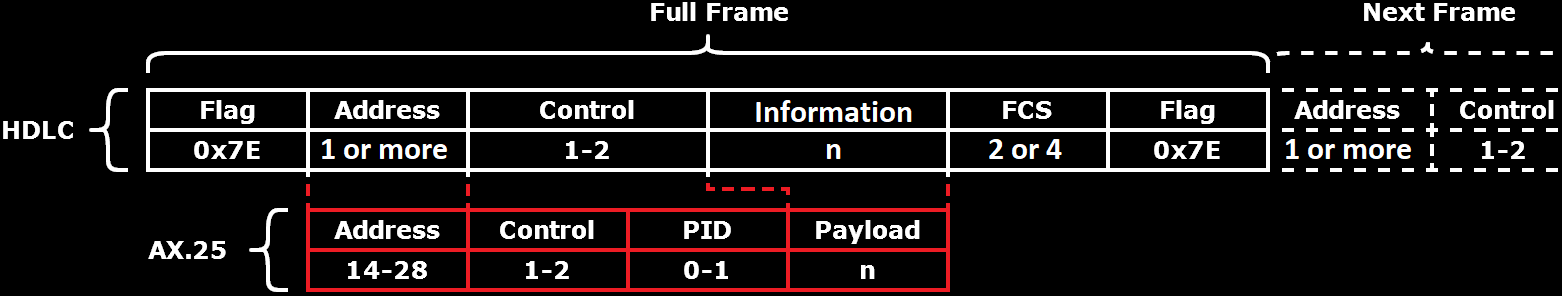
AX.25 is a data link layer (2nd OSI Layer) derived from the X.25 protocol, which in it’s part is derived from the HDLC standard. AX.25 is designed for use by amateur radio operators. It is also used by the APRS system. The AX.25 standard is defined here. At its core it uses HDLC frames and adds to it the definition and semantics of all the fields. It also defines the FCS used, the 16-bit CRC-CCITT.
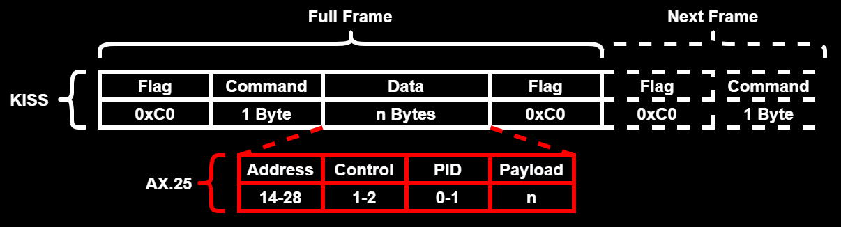
Bellow is the structure of a AX.25 frame with all the fields and how they fit into the underlying HDLC frame. Length of each field are in bytes:
Address Field
AX.25 defines that the address field is composed of multiple addresses. First the destination address, followed by the source address and then one or two optional repeater addresses. The end of the complete address field is indicated by a “1” in the least significant bit of the last byte of the last address. For this system to work, all address bytes have to be left shifted by one bit to make space for this bit. Each address field is seven bytes long and consist of the radio amateur callsigns, plus an additional byte for the SSID. Unused bytes are filled with the “space” character (0x20), eg. when the callsign is shorter then 6 characters/bytes.
Radio amateur callsign only contain letters and numbers. They are composed of a prefix that is up to three characters long and which is assigned by the ITU for each country to distribute/use. This is followed by a single separating numeral, a digit from 0 to 9. And then the suffix, up to 5 characters long, which uniquely identifies each radio amateur and ground station. Sometimes a second suffix is used to identify different stations operated by the same amateur radio operator. In general, the base callsigns are up to 6 characters long but ITU defines the maximum length to be 7 characters. These callsigns can’t be used in AX.25 as the 7th byte is used for the SSID.
The SSID field is a 4-bit long number, 0 to 15, which allows for a radio amateur to operate more then one AX.25 station, kind of like a port address. The next, higher, two bits can be used in individual networks but are generally unused and set to “1”. The last and most significant bit is the command/response bit, explained in the documentation on page 45 (to remember that the whole field is left shift by one bit).
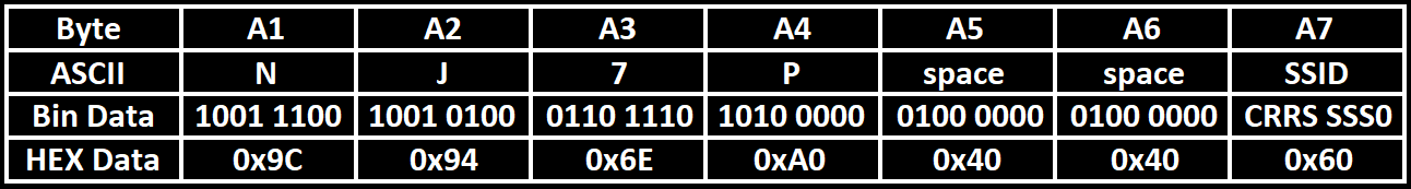
Bellow is an example of the destination address, the first address. This is always followed by the source address and therefore the last bit in the last byte (byte 7 aka SSID) is set to “0”. The different bits in the SSID field are shown in the “Bin Data”: “C” for the command/response bit, “RR” for the optional and usually set to “1” bits, “SSSS” for the SSID 4-bit number and, finally, the end of address field bit.
Control Field
The control field is used to identify what type of frame is being sent and also to transmit commands and responses from one end to the other. There are three general frame types: Information frame (I frame), supervisory frame (S frame), and unnumbered frame (U frame). I frames are identified by the bit 0 of the control field being set to “0”, S frames by the bit 0 set to “1” and bit 1 to “0” and lastly, U frames by bit 0 set to “1” and bit 1 set to “1” a well. The meaning of the remaining bits are different for each frame type.
A good source for more info about each type of frame and the meaning of each bit can be found in the documentation on page 26.
PID Field
The Protocol Identifier (PID) field is used only with information frames (I frames) and indicate what layer 3 protocol is used, if any. The definition of the PID field can be found in the documentation on page 17.
KISS stands for “Keep It Simple, Stupid” and is not only a design principle, but also one of the most used Host-to-TNC communication protocols in HAM Radios. It is a very simple protocol that standardizes the transmission of data, normally AX.25 packets, over a asynchronous serial link, like RS232 or UART. It allows the transmission any arbitrary data, with no length limitation. Its complete definition can be found here.
A KISS frame consists starts with a start flag, the FEND (Frame Escape, 0xC0), used for frame delimiting and synchronization similar to the HDLC/AX.25 flags. This is followed by a command byte, which in its lower 4 bits holds the command code and in the upper the port number, used in multi-port TNCs. The most important commands are 0x00, indicating that it is a data frame, and 0xFF, used to exit the KISS mode in a TNC. The command byte is then followed by the payload, the data bytes to be transmitted. And finally the end flag, which is the same as a start flag, FEND (0xC0). Back-to-back FEND flags are to be ignored and not interpreted as empty frames.
Because the protocol allows any type of message to be transmitted over it, any bytes are valid, it is necessary to handle FEND (0xC0) bytes in the payload to avoid wrong start/end flag interpretations. This is done by substituting, escaping, any FEND bytes in the payload by a FESC (Frame Escape, 0xDB) character followed by a TFEND (Transposed Frame End, 0xDC), and any FESC (0xDB) byte by a FESC (Frame Escape, 0xDB) character followed by a TFESC (Transposed Frame Escape, 0xDD).
Bellow is the structure of a KISS frame with all the fields and how a AX.25 packet fits into it (attention that the AX.25 frame is without HDLC, e.g. without bit stuffing and flags).
As an example for a KISS framing, consider that we want to send the message “NotBlackMagic” to a TNC on port 2. This is transmitted as:
0xC0, 0x20, 0x4E, 0x6F, 0x74, 0x42, 0x6C, 0x61, 0x63, 0x6B, 0x4D, 0x61, 0x67, 0x69, 0x63, 0xC0And as an example for character escaping, consider that we to send the message 0xAA 0xC0 0xAB 0xDB 0xFF to a TNC on port 0, and which will be transmitted as (notice the substitution of bytes 0xC0 and 0xDB):
0xC0, 0x00, 0xAA, 0xDB, 0xDC, 0xAB, 0xDB, 0xDD, 0xFF, 0xC0High-Level Data Link Control (HDLC) is a bit-oriented data link layer (2nd OSI Layer) mainly used to connect one device to another. HDLC does not specify the full semantics of the frame fields and there are different implementations for them. It does define how the bytes, and bits, are transmitted and how a frame is delimited. Each frame is delimited by a flag byte (0x7E) with the end flag also marking the beginning of the next frame, if there is one, meaning that between two consecutive frames only one flag byte appears. Bytes are transmitted with the least significant bit first (LSBit), contrary to most other protocols.
Because the flag bytes consist of six consecutive “1” it has to be ensured that the frame does not contain this sequences. This is done by using bit stuffing, any time five consecutive “1” appear a “0” is inserted, breaking the sequence. On the receiving end, every “0” that appears after five “1” has to be remove. If instead six consecutive “1” appear this signals a flag byte if the next bit is a “0”, or an error if it is another “1”. In the later case the frame is aborted and the hunt for a new start flag begins again.
A HDLC frame generally consist of the following fields, with the number of bits for each field indicated bellow each field:

Data is usually transmitted in 8 bits, 1 byte. The FCS uses a 16-bit CRC-CCITT or a 32-bit CRC-32 computed over the whole frame, excluding the frame delimiter flags. How long and what the meaning of the content of the other fields are is not defined in the HDLC specification. This allows different standards to define different semantics and lengths of these fields, like AX.25.
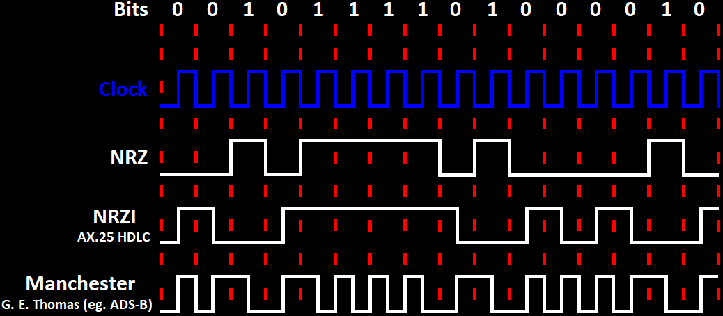
Encoding is the method used to represent the information to be transmitted (bits). The most commonly used and simple encodings are Non-Return-to-Zero (NRZ), Non-Return-to-Zero Inverted (NRZI) and Manchester. Sometimes, in addition, a scrambler is also used.
Non-Return-to-Zero (NRZ)
The simplest encoding scheme is NRZ where each bit is encoded into a significant condition/state. In circuits this is usually a positive voltage for “1” and a negative voltage for “0” with no neutral or rest sate like 0 volts (GND), which is where the name comes from. In radio communications, the two conditions depend on the modulation used, eg. in (B)FSK the “0” and “1” are represented by two different frequencies.
Non-Return-to-Zero Inverted (NRZI)
In NRZI the bits are encoded into the presence or absence of a transition at a clock edge, normally in the middle of a bit period. Generally, the “1” bit is encoded as a transition and the “0” bit as no transition. In HDLC this is the opposite way, the “0” is encoded as a transition and the “1” as none. Encoding bits as the presence or absence of transitions means that the receiver doesn’t have to know what each level/state encodes, eg. if a positive voltage represents a “0” or a “1”, only that a transition means a “1” and none transition a “0” (or vice-versa). This is very important in modulations like (B)PSK, this because it is very hard to know the absolute phase of the signal but it is very easy to detect a phase shift.
Both NRZ and NRZI don’t solve the problem of long sequences of no transitions. These are very hard for a receiver to decode as there is no way to correct the bit-clock and therefore correctly count the number of bits. In case of HDLC (and AX.25), which as seen uses the “0” to encode a transition, a long sequence of “1” would be a problem but these are removed by bit stuffing, as already seen. Bit stuffing forces a transition after a sequence of five consecutive “1” by inserting a “0”.
Manchester
Manchester encoding solves the problem with long sequences of no transition by encoding each bit as a transition in the middle of each bit period. There are two contrary conventions to how the bits are represented:
-
The first convention was published by G.E. Thomas. It specifies that a “0” bit is encoded as a transition from low to high and a “1” bit as a transition from high to low. This is the convention used in ADS-B.
-
The second is defined in the IEEE 802.3 (Ethernet) standard. Here the “0” is encoded as a transition from high to low and a “1” bit as a transition from low to high.
The guarantee of a transition for each bit significantly improves the bit-clock recovery on the receiver. The drawback is that this encoding effectively doubles the transmitted bits, each bit is encoded into two, and therefore it requires double the bandwidth then the simpler NRZ or NRZI encodings.
Bellow is a figure showing the different encodings. For NRZI, the AX.25 HDLC convention is used and for Manchester, the one used by ADS-B.
Scrambler
As already discussed, receivers have a hard time to decode the incoming signal if there are no frequent transitions, long sequences of a single state like “1”. As seen above, Manchester encoding solves this by forcing a transition for every bit but has the drawback of doubling the required bit-rate and therefore bandwidth. A different way to solving this is using a scrambler. A scrambler randomizes the incoming bit-stream in a deterministic way so that it can be recovered at the receiver. There are two main types of scramblers:
-
Additive (synchronous) scrambler: This scrambler performs a modulo-two addition between the input stream and a pseudo-random binary sequence which can be a pre-calculated sequence or, more often, generated by a linear-feedback shift register (LFSR). This type of scrambler needs to be synchronized, the LFSR has to be initialized/loaded with a pre-defined initial state.
-
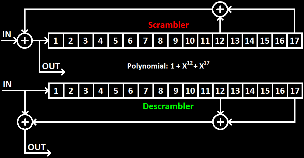
Multiplicative (self-synchronizing) scrambler: This scrambler, often called feed-through, is called multiplicative because it performs a multiplication of the input stream by a transfer function in Z-space. A very complicated way of saying that this scrambler is recursive, the output of the modulo-two is feed into de LFSR in the scrambler. They don’t need synchronization, the descrambler only needs N-bits, with N being the length of the LFSR, to be synchronized/initialized, to flush the LFSR. The draw-back of this type of scrambler is error multiplication, a single bit error at the descrambler input results in X errors in the output, with X being the number of feedback taps.
Both scramblers are defined by a polynomial which defines which positions in the LFSR are used as taps. The additive scrambler is also defined by it’s initial state.
Bellow is a figure showing the multiplicative (feed-through) scrambler, and descrambler, with the polynomial $ 1 + x^{12} + x^{17} $. This is the scrambler and polynomial used in FSK-9600 (G3RUH) and many other digital modulations.