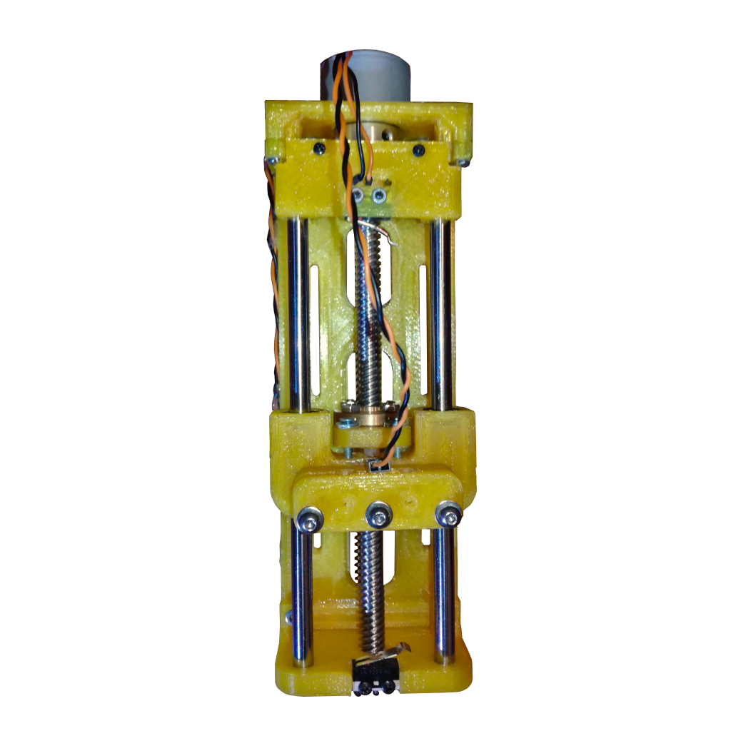

This project was developed during the NXP HoverGames3 as part of my submission project AutoSQA. It was designed with the objective of driving a soil sensor into the soil and measuring the required force, and with that the stiffness of the soil. The design I came up with is this 3D printed 1-Axis linear actuator, with a travel distance of around 110mm, and a membrane type force sensor to sense the actuation force on the moving carriage. The full dimension of the actuator, including the stepper are 200x70x50mm, while the actuation travel limits are around 110mm.
The project consists on the linear actuator hardware itself, a mostly 3D printed 1-Axis linear actuator with a two part carriage to enable the actuation force sensing, as well as a simple controller board made up of an Arduino Pro Mini and the DRV8824 stepper motor driver soldered to a protoboard.
This project with all its 3D printed parts can also be found on my Thingiverse page.
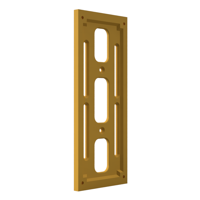
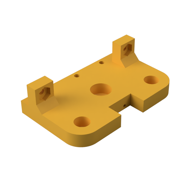
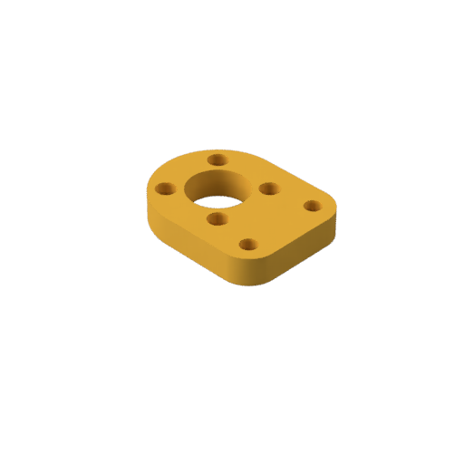
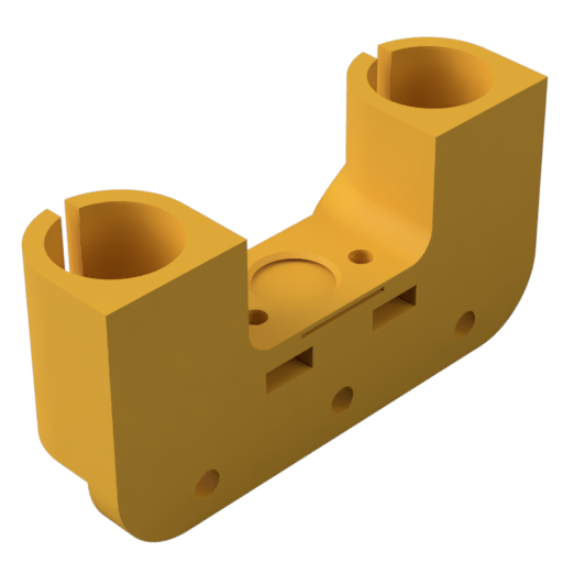
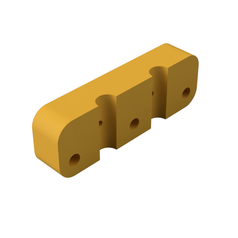
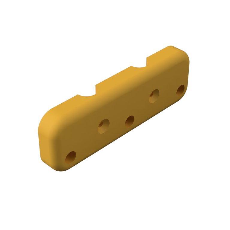
Bellow is an exploded view of the linear actuator with all the mechanical parts, without screws or nuts or any of the electronics, visible. The main frame is 3D printed (orange parts) and are assembled together with M2.5 countersunk screws. The step files for these parts are available to download in the Parts section. The other mechanical parts, linear rods, lead screw and screws, are easily found on eBay and/or AliExpress and are also listed in the Parts section.
Parts
As mentioned and can be seen in the section above, the linear stage structure is made from 3D printed parts assembled together with M2.5 screws. In addition to those, some mechanical parts and electronics, have to be acquired. Bellow is the full parts list, both the 3D printed parts (.stl files) and not.
3D Parts
All 3D printed parts are optimized to reduce overhangs and size, preference was given in splitting parts up to facilitate printing. For the shown (my) linear stage, the parts were 3D printed in PETG giving the parts good physical strength and flexibility, in contrast to PLA which is very rigid. Other plastics can also be used, like ABS or PLA.
Mechanical
List of all none 3D printed parts required for the linear stage:
- Smooth Rods (x2): 150mm long and 6mm diameter
- T8 Lead Screw and Nut (x1): 150 mm long
- Linear Bearing (x2): LM6UU with 6mm inner diameter
- Coupler (x1): Coupler from 8mm to 6mm rods
- Stepper Motor (x1): Either 28BYJ-48 or NEMA14
- Leaver Switch (x2): Standard leaver switch used as endstops (3D printers and CNC)
- Screws: Assortment of M2.5 screws and nuts
Electronics
List of all required parts for the linear stage controller:
- Pressure Sensor (x1): Membrane type pressure sensor (load cell) with 4mm diameter for 50g-2kg and amplifier board
- Controller MCU: Arduino Pro Mini 5V model with 16MHz (or other ATMega328 base board)
- Stepper Controller: DRV8824 or A4988 (or other compatible)
- Protoboard: Double layer with a size of 35x55mm or larger
- JST-XH Connectors: 3x 2-pin, 1x 3-pin and 1x 5-pin
- Wires
- USB to UART bridge: CP2102 based module
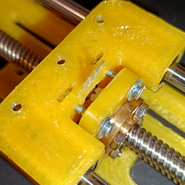
Force Sensing
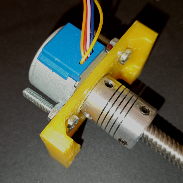
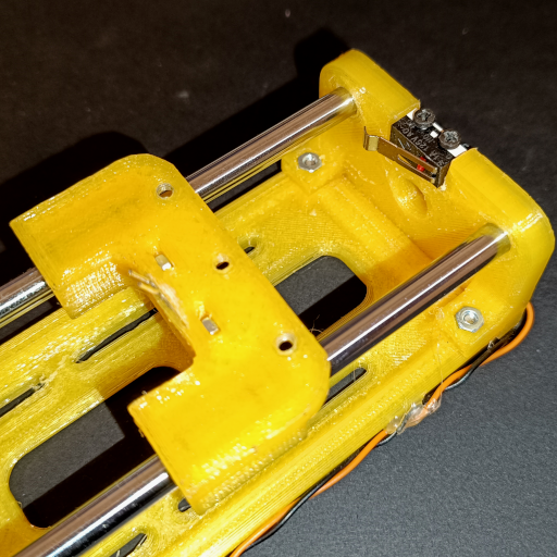
The force sensing is achieved by using a free moving carriage and a pusher mounted to the lead screw nut. The pusher is connected to the carriage by two screws, but with play, so that it can move slightly up and down without moving the carriage. The carriage has the membrane pressure (force) sensor embedded into it, at the contact point with the carrier pusher. This means that when the carriage pusher pushes the carriage, the force sensor is in-between the two parts and can measure the force used to push the carriage. The screws are required to keep the pusher from rotating, and to be able to pull the carriage back up. There is no force sensing in the upwards movement. This assembly is shown in the figure bellow:
Assembly
The assembly of the linear actuator is quite simple, as long as the steps are followed in order:
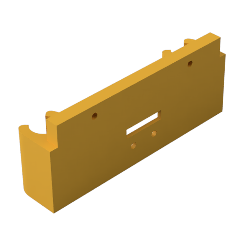
Step 1: Stage Bottom
The first step is to mount the bottom stage piece to the stage backbone. The bottom stage piece can be mounted on either ends of the backbone as this piece is symmetric.
The bottom piece is fixed to the backbone with two M2.5x10mm screws and nuts.
With the bottom piece fixed in place, the bottom endstop can be mounted and fixed in place with two small M2x6mm screws.
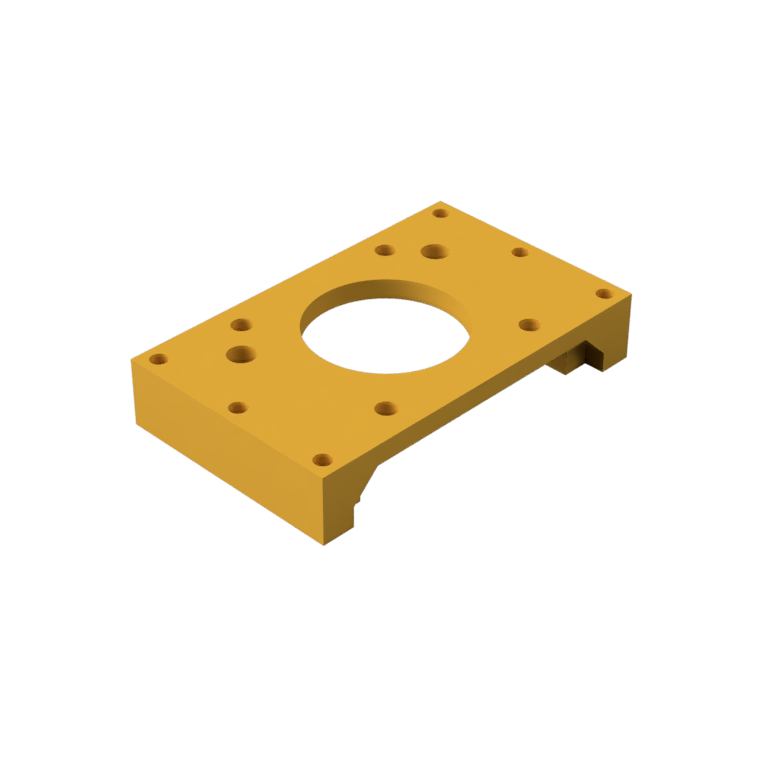
Step 2: Mount Motor
The next step is to mount the stepper motor to the motor holder plate. If the stepper used is the 28BYJ-48 then it is mounted with two M4 screws and nuts. If a NEMA14 is used then four M3 screws are used.
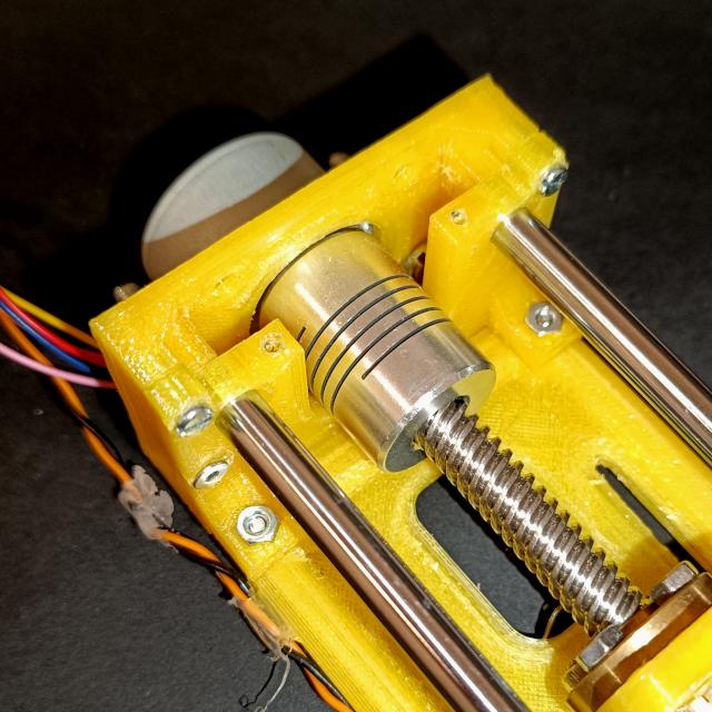
After the motor is fixed to the motor holder plate, the lead screw can be mounted to the motor with the use of the coupler.
Step 3: Carriage Pusher
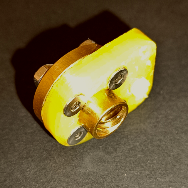
Next the carriage pusher is assembled. The lead screw nut is fixed to the carriage pusher piece with four M2.5x10mm screws and nuts, with the small hill part facing away from the lead screw nut.
With the carriage pusher assembled it is now added to the lead screw. Important that the the lead screw nut faces the motor, the carriage pusher piece away from the motor.
ATTENTION: It can be necessary to drill out the "hill" of the carriage pusher and replace it with a plastic M3 screw as the hill might not make good contact with the force sensor (done here)!
Step 4: Prepare Carriage
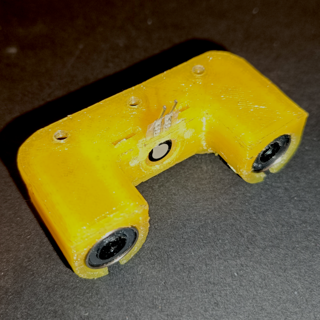
Now we can prepare the carriage itself. Starting by gluing the force sensor in its slot in the carriage (which way faces outside doesn't matter). Glue is only applied sparsely and to the bottom side, the side facing the carriage. After letting the glue dry, the linear bearings are inserted into the carriage.
At this point it is recommend to add all necessary nuts to the carriage as later they will be harder to access. The carriage takes five M2.5 Nuts, two in slots on either side of the force sensor (for the carriage pusher) and three on the bottom side used to mount payloads (these my need a drop of glue to stay in place).
Step 5: Mount Motor Mount
The motor assembly can now be finished, by screwing the motor holder piece (with the stepper) to the top stage piece with four M2.5x10mm screws.
Attention here that the motor holder piece is not symmetric, one side has larger inside corners that are intended to partially cover the linear rods holes in the top stage piece.
Step 6: Linear Rods
With all the individual parts prepared, the whole stage can now be assembled. First the linear rods are inserted into their respective holes in the bottom stage piece and the carriage assembly slid onto the linear rods.
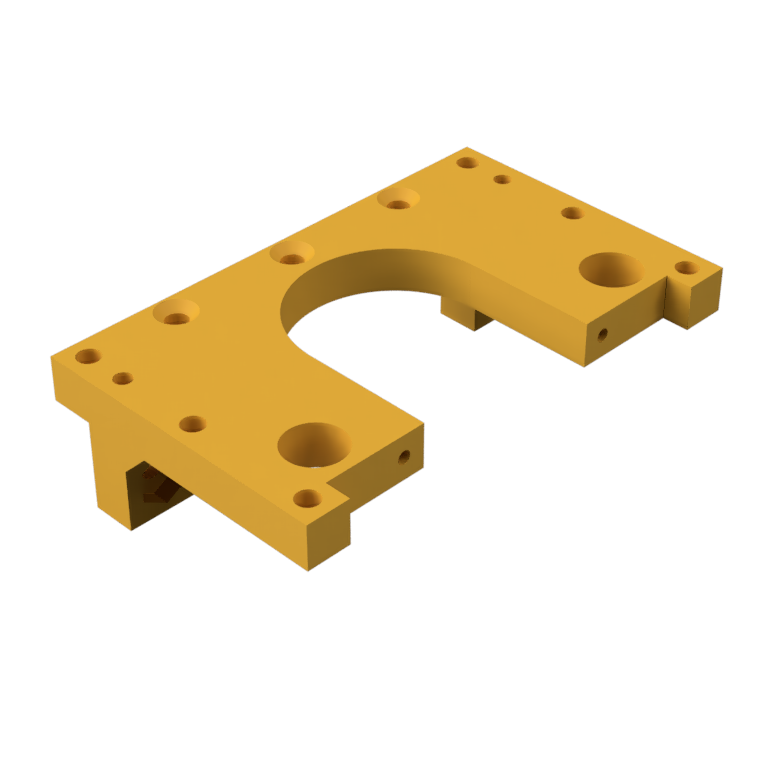
Step 7: Stage Top
Next we take the motor mount, with the stepper, lead screw and top stage piece assembled, and mount it to the backbone. For this first insert the two linear rods into their holes in the top stage piece and the lead screw into its bottom piece cutout. With this, the top stage assembly should line up with the holes of the backbone and can be fixed in place with two M2.5x10mm screws and nuts.
This should now fix the linear rods and lead screw in place, and finish the main stage assembly.
Step 8: Fix Carriage Pusher
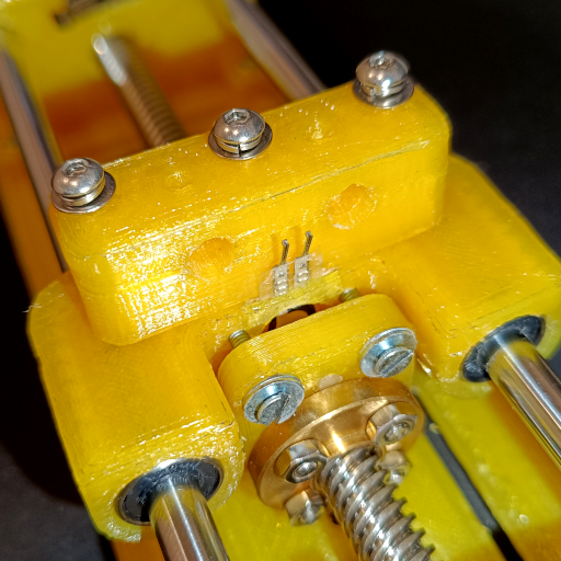
Now the carriage pusher can be fixed to the carriage with two M2.5x15mm screws. Attention to that their must be some play between the two parts, the carriage pusher should be able to move away from the force sensor slightly so that the force sensor is only pressed on a downwards motion.
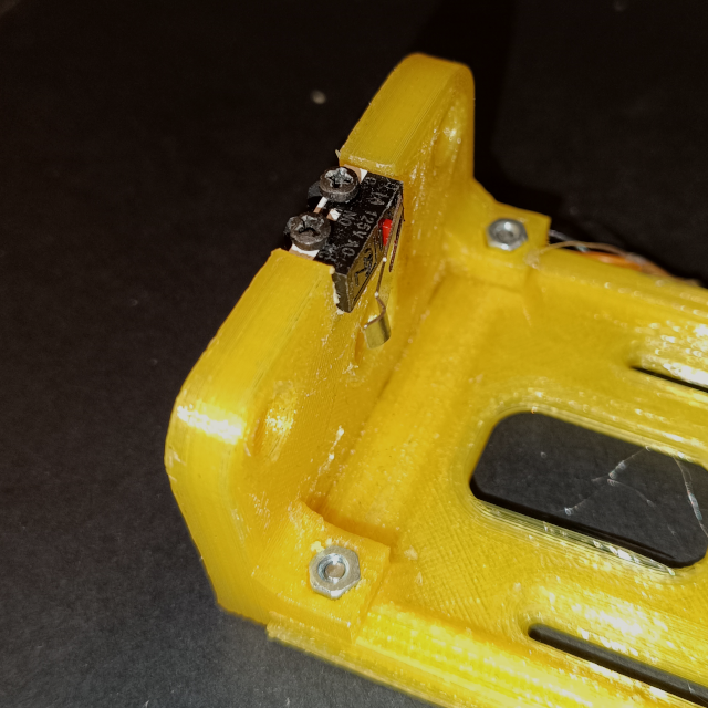
Step 9: Top Endstop Mount
The last thing left to finish the linear stage is to add the top endstop. For this mount a endstop to the top endstop mount, with two small M2 screws and then clip the mount onto the linear rods. Fix it to the top stage piece with two small M2x6mm screws.
Step 10: Adding Payload
With the linear stage assembled, the desired payload can now be mounted to the carriage, using the integrated three M2.5 mounting nuts.
Here the payload is a soil sensor, mounted to the carriage with a specially designed two piece holder.
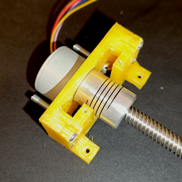
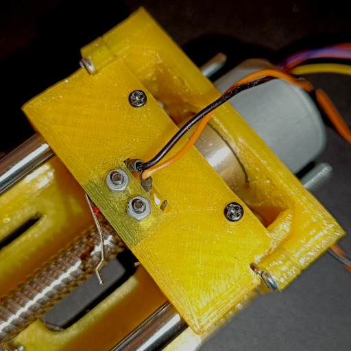
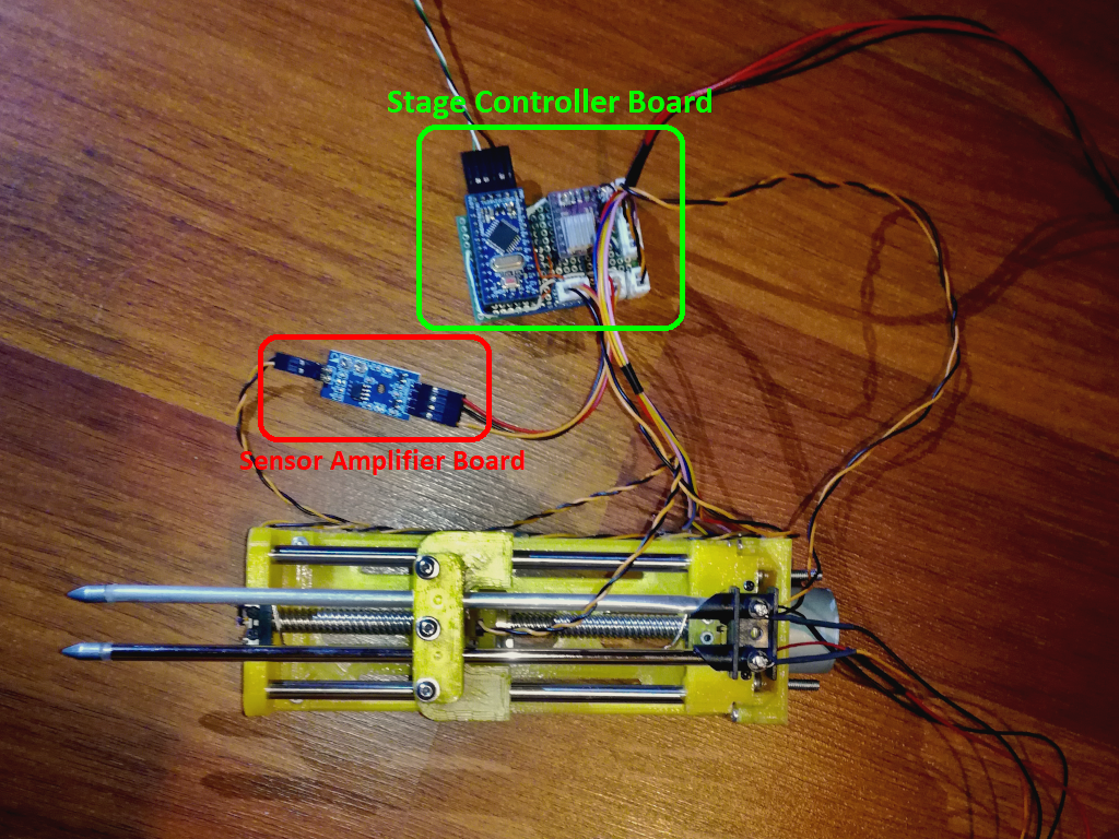
This concludes the assembly of the linear stage. The next step is to wire it all up e.g. to the stage controller board. The force sensor to its amplifier board and then to the stage controller board as well as the two endstops and the stepper motor. See the picture bellow for a clearer view of the wiring.
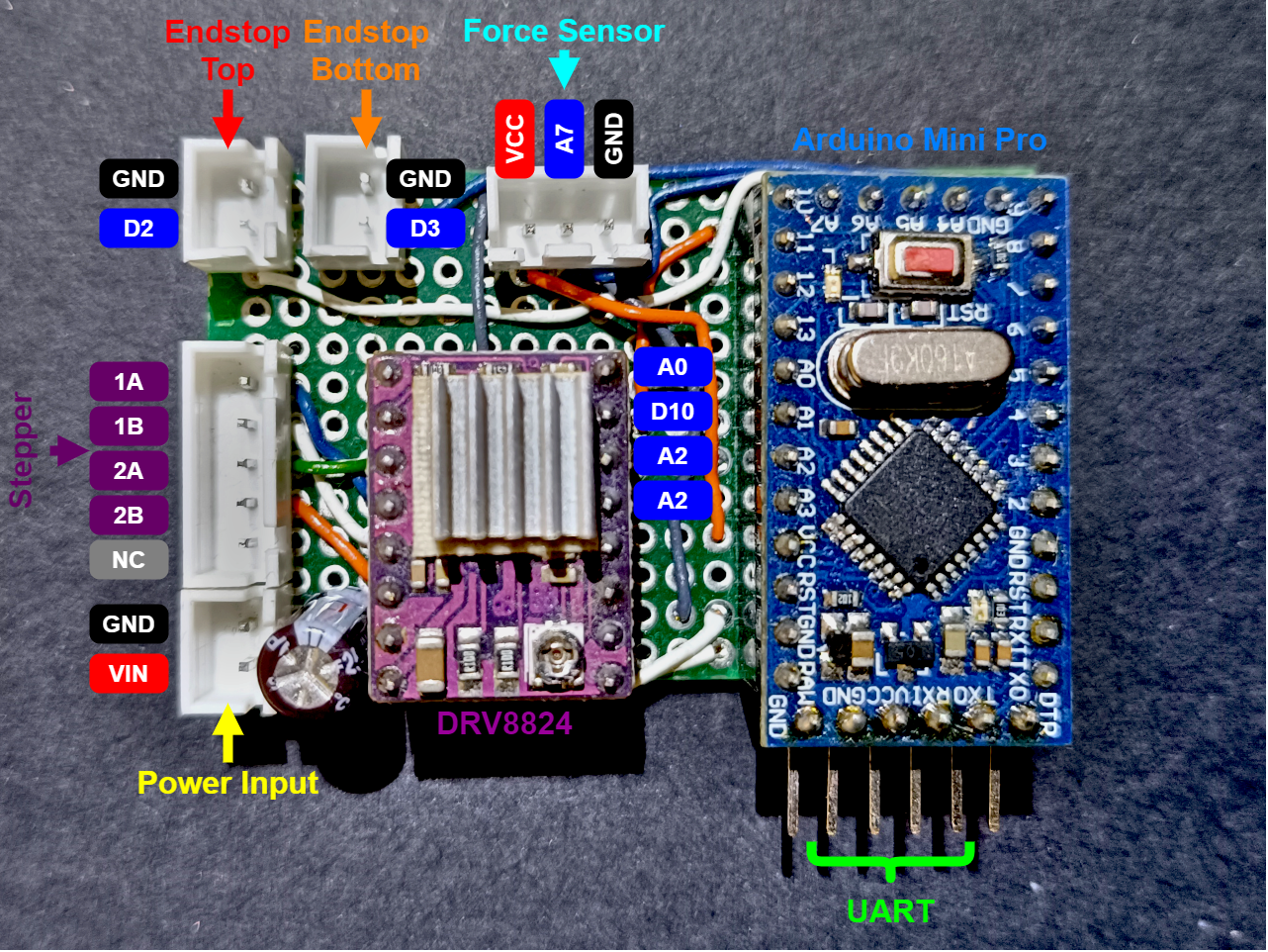
This section describes the developed electronics hardware for the linear stage, the controller board. The controller board, as the name suggests, controls the linear stage by taking in ASCII style commands over UART. This board is very simple and is made up of an Arduino Pro Mini and an DRV8825 stepper driver. The control of the 28BYJ-48 stepper, using the DRV8825 driver, is based on this blog post. The whole controller board is assembled on a protoboard with soldered wires used to interconnect all parts. Bellow is a picture of the controller board, with labels showing to what each connector connects and how the different parts are connected to the Arduino Pro Mini, to which pins:
A small detail that I overlooked here is that this stepper driver, the DRV8825, only works with supply voltages above 8V, so when it is powered from a 2S lipo like in my Hovergames3 project, it only works with an almost fully charged battery (2S lipo fully charged have 8.4V). Additionally, the 28BYJ-48 stepper motor is a 5V part so the stepper driver overdrives the motor a bit. The DRV8825 is not really suitable for the 28BYJ-48 stepper motor and a Nema14 should be used instead (it also has more torque). From my testing it doesn’t seem to be a problem, even with no current limiting the motor does not get warm in the relatively short time it takes for one full motion (top to bottom or vice-versa). Also, the stepper driver is disabled when not moving to avoid over-driving the motor more then needed.
The controller board has two inputs for endstops, top and bottom, so that the controller knows when the limits of the linear stage are reached, for safety and for homing. Finally, this board also samples the force sensor, the amplifier board output, and aborts any actuation if the force is above a defined threshold e.g. before the stepper motor would stall or, for my Hovergames3 project, the force value that would start to lift the Buggy.
Control of this board, of the Arduino, is done over a serial (UART) interface with simple ASCII style commands.
As seen in the previous section, the linear stage controller uses a Arduino Pro Mini (ATmega328p). The firmware was developed with the Arduino IDE and is available to download bellow.
Firmware: SoilSensorStage.ino
Communication Protocol
The communication interface used by the linear stage controller, to the Arduino Pro Mini, is a simple serial/UART interface using the standard 8-N-1 settings and a baudrate of 115200. To connect the controller to a PC a USB to UART adapter/bridge is required e.g. a module based on the CP2102. Commands to the controller are sent in ASCII format, with the first character identifying the command type and the following characters an optional, depending on the command, single integer parameter. The command is terminated with a “;” character. Answers from the controller to commands are just the requested value(s), all integers, in ASCII format, separated by “;” when their are multiple return values and terminated with a new line, “\n”, character. The following commands, with their respective answers and parameters when applicable, are available:
- Homing (“H;”, no parameter): Moves the carriage to the top endstop and zeros the position variable.
- Move Up (“Uxxx;”, mm to move): Move the carriage the desired amount up, in mm.
- Move Down (“Dxxx;”, mm to move): Move the carriage the desired amount down, in mm.
- Move Stop (“S;”, no parameter): Stops the current carriage movement.
- Get Info (“I;”, no parameter): Requests all the linear stage status/info parameters: If homing (0: No; 1: Yes), current position (in mm), maximum force applied during current movement (in kPa), if maximum force exceeded (0: No; 1: Yes). These are returned in that order and in the format “a;bbb;ccc;d\n”. Both the maximum force applied and maximum force exceeded flag are reset when a movement command is given.
- Get Force (“F;”, no parameter): Requests the current force value in kPa. Returned as a ASCII integer.
- Get Position (“P;”, no parameter): Requests the current position value in mm. Returned as a ASCII integer.
Two experiments were performed to analyze the performance and to calibrate the linear actuator. The first experiment was to determine the maximum steps per second, under load, the 28BYJ-48 stepper can support before loosing steps. The limit turned out to be around 1250 steps per second or 800 us between steps, above this value the stepper looses steps under heavier loads. Also, 1250 steps per second is only achieved reliably when the steps per second are ramped up and not just set. The steps per revolution of the stepper was not determined experimentally and was taken from a blog post: The stepper has 32 steps per revolution and a reduction gear of 1:64 meaning that the output steps per revolution is 2048. This means that driving the 28BYJ-48 stepper with the DRV8825 driver and using a 2S lipo (~8.4V), the stepper has a maximum usable RPM of \({{1250 \over 2048} 60} = 37 RPM\), more then double of the 15 RPM mentioned in the blog post (not overdriven there). This gives the linear stage a maximum travel speed of 148 mm/min, or 2.5 mm/s, with the 4mm pitch lead screw used.
The other experiment performed was determining the response curve of the force sensing. For this the output voltage (in ADC counts) of the membrane pressure sensor, after the amplifier board, is measured with different loads/weights on it. For this, the linear stage was mounted to the MR-Buggy3, the soil sensor mounted to the carriage and a scale placed under the soil sensor probe. Bellow is a picture of this setup:
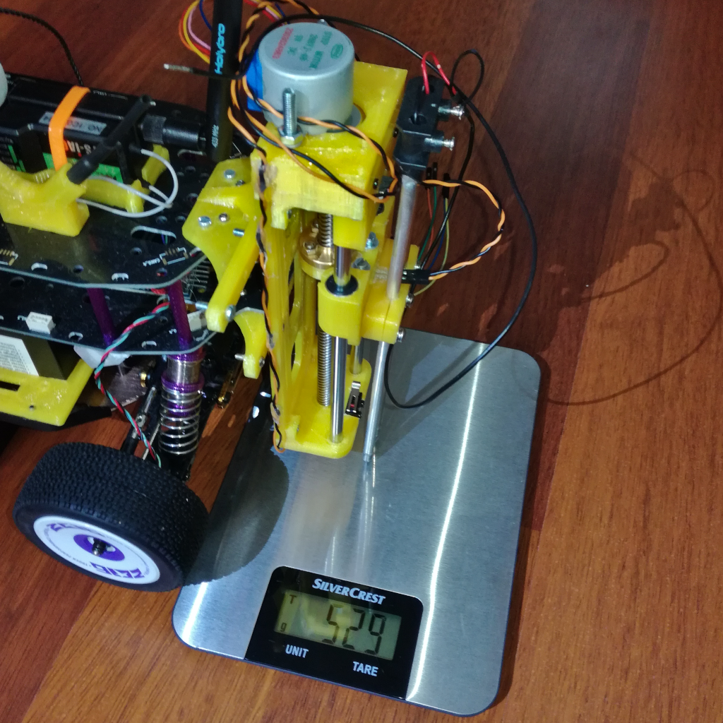
Different weights were then added on top of the buggy and both the scale output, which measures the amount of force applied to the linear stage carriage, and the force sensor output are recorded. The force is just the measured weight from the scale converted to Newton (N) using Earths gravity, \( F=ma=m \times 9.8 (N)\), while the pressure (in Pa) is calculated assuming a flat circular cross-section for the soil probe, \(P={F \over A}=F \times 0.00007854 (Pa)\). The result of this test is shown in the graph bellow:
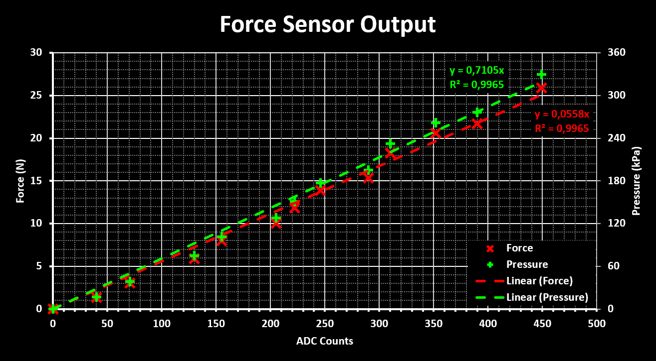
From this we gather that the response of the pressure sensor is very linear with the force applied to it, which is great! A small additional test that was performed was to see what the maximum force that the linear stage can support, at what actuation force the motor stalls. This value is around 400 kPa, or 33 N, and therefore, to be on the save side, the actuation force limit is set to 350 kPa.