
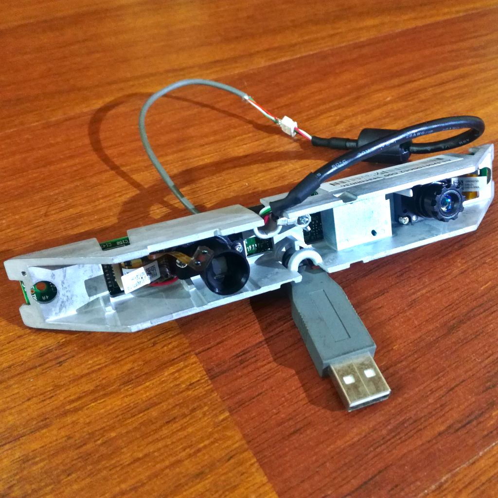
As with many of the parts found in this section, I found this Depth Vision Module during a random AliExpress search in a store page of my favorite seller that sells recovered parts from consumer electronics. This Depth Vision Module was sold for 17€ including shipping, when I bought it, and comes barebone with no cover and no complete USB cable, and of course no working guarantee. From the listing we get that it has an IR dot matrix projector and an IR camera do capture the reflected IR dot pattern which is then used to compute a depth map. This is the same technique used in the original Kinect for the Xbox 360. The module looks like the core of a ASUS Xtion PRO (not LIVE which has an additional RGB camera) that can also be found on AliExpress for around 120€.
After getting the module and looking at its ICs, I found the core IC responsible for all processing, a PrimeSense 1080 from the company of the same name PrimeSense. This was the company that developed the chip for the Kinect, and it was latter acquired by Apple in 2013. So this is the company that gave Apple the expertise for there 3D mapping cameras, now used for FaceID and Memojis.
The software used to interface with the module is OpenNI 2.2, a open source software project founded in part by PrimeSense and shut down after the acquisition by Apple. Luckily it was forked and the forks kept by other partners with the source code still available. This software can also be used with the ASUS Xtion modules, an indicator that this module is actually a ASUS Xtion. This is reinforced by the label found on the module, identifying it as being from ASUSTek (ASUS). Therefore, if we consider it is a ASUS Xtion Pro, it should have a maximum resolution of 640x480 with a maximum frame rate of 60 fps (at 320x240) and a detection range between 80 cm and 3.5 meters. It should also have 2 microphones, will see if this is actually the case here…
Other Depth Vision Modules
Besides the PrimeSense camera and its close relative, the Kinect V1, there are a lot of other depth sensing camera systems available. The below table list just a few of them, focused on versions that are easily available for cheap on sites like eBay e.g. the Kinect and the PS Cameras.
| Feature | Kinect V1 | Kinect V2 | PS4 Camera V1/V2 | PS5 Camera | ASUS Xtion |
|---|---|---|---|---|---|
| Technology | IR Dots Matrix | IR Dot Matrix | Stereo | Stereo | IR Dot Matrix |
| Depth Processing | On Board | On Board | Off Board | Off Board | On Board |
| Color Camera | 640x480 | 1920x1080 | 1280x800 | 1920x1080 | 1280x1024 (Live) |
| Depth Camera | 320x240 | 512x424 | 640x480 | ||
| Max. Depth | 4.5 m | 4.5 m | 3.5 m | ||
| Min. Depth | 40 cm (near mode) | 50 cm | 30 cm | 80 cm | |
| Horizontal FoV | 57 deg | 70 deg | 75 deg | 58 deg | |
| Vertical FoV | 43 deg | 60 deg | 51 deg | 45 deg | |
| USB Standard | USB 2.0 | USB 3.0 | USB 3.0 | USB 3.0 | USB 2.0 |
OpenNI NiViewer
After adding an actual USB connector to the cable and installing OpenNI, we can open the viewer that is installed alongside it, the NiViewer. This then shows a full screen side-by-side view of the depth information and the IR camera output. Full screen mode can be exited with the “F” key or through the options menu opened by the right mouse button. Inside that menu there are all the available options/configurations, some are not functional with this module (RGB camera stuff) and other break the stream. Starting with the resolution options, for the depth information we have 160x120, 320x240 and 640x480, with an option for a 1mm or a 0.1mm depth resolution, and a fixed frame rate of 30 fps with exception of the 320x240 which has an option for both 30 fps and 60 fps. From my tests only the 160x120 and 320x240 resolutions at 30 fps can be used, for both the depth and IR frames, with the viewer frames freezing with higher frame rates or resolutions… With the 320x240 resolution at 30 fps it works quite well, with smooth frame streaming and display. This is the option used in the figure shown below:
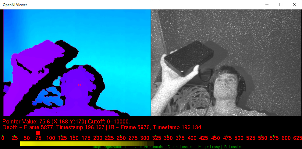
In this figure, the right frame shows the depth information encoded into rainbow color while the left frame shows the black and white image from the IR sensor. In the later we can also see the reflected IR dots from the IR dot matrix projector, which look like noise. Additionally we can se some information about the pixel under the cursor, the red text below the frames, which can be enabled in the options menu (right mouse button). The depth information can be shown in a few different styles, different depth values to color translation, shown in the figures below:


There are some additional options like image mirroring, options for RGB modes (not applicable for this module), and IR frame representation (with or without depth information masking) but the ones mentioned and shown above are the main ones.
OpenNI Python
To get raw access to both the depth and IR frames from the module with Python, the Python package openni 2.3.0 can be used. This package provides Python-bindings for OpenNI2 and NiTE2. With this we can setup and get two data (frame) streams from the Depth Vision Module, one for the actual depth information and one for the IR camera data. There is also an option for a RGB stream, but this module does not have an RGB camera so this stream is unavailable. The depth information is returned as a 1D array of 16-bit data, with only the lower 12-bits actually used and with the depth distance in mm.
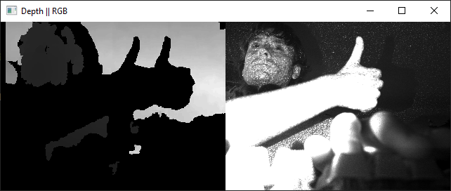
Both data streams, depth and IR, can then be reshaped from the 1D array to a 2D array (how an image is normally organized) with NumPy. NumPy can then also be used to scale the values of both the depth and IR frames to a range between 0 and 255, 8-Bit data, which can then be converted, and displayed, to an actual frame/image with OpenCV for Python. With both frames displayed side-by-side, this results in the figure shown below:
This code was developed with help from a Stack Overflow post and a GitHub repository, and is available for download in the link below. This code can serve as a basis to interface with this Depth Vision Module, the data can then be used for further processing and incorporation into some application. I have planned to study and implement a ROS 2 package/node based on this code.
Code: openni_test.py
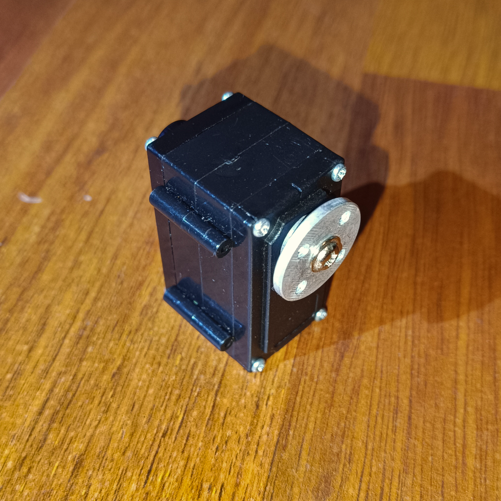
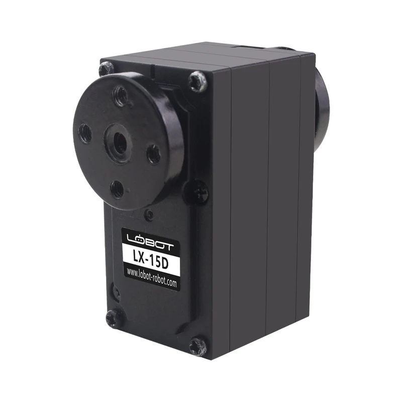
In the same shopping spree as the Depth Vision Module I also bought a serial bus servo, from the same seller. This Serial Bus Servo costs, at the time of writing, just under 6€ including shipping. As with most things sold by this seller, this is probably a recovered or “old” stock part and comes with minimal information. Based on this sparse information, we get that it is a serial bus controlled digital servo that can be daisychained, but no information on the manufacturer or the used protocol. These types of servos are mostly used in robotics applications where a lot of servos are used and therefore the daisychaining simplifies wiring, and control, a lot.
Trying to find the manufacturer of the servo, and with that the used interface protocol, is also not made easier by the lack of any kind of markings on the server itself, no markings for the manufacturer or model number… The only hint we get is a small note in the AliExpress listing that more information about the servo can be found on Gitee, a chinese GitHub style website. Being a chinese website also means that most projects hosted there are exclusively in chinese… With the help of Google Translator I found a very promising project repository, which includes the descriptions, code and datasheets for a Xaobao servo that matches the looks of my servo.
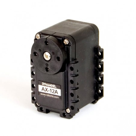
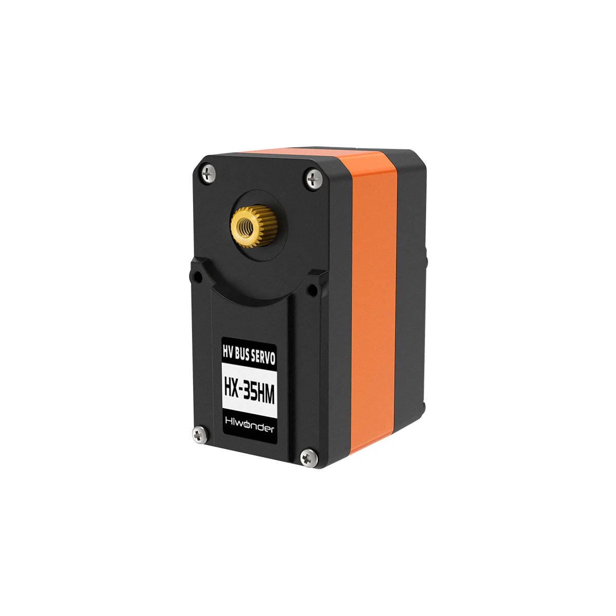
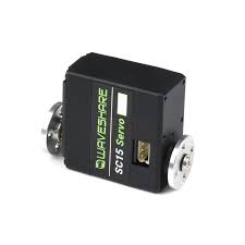
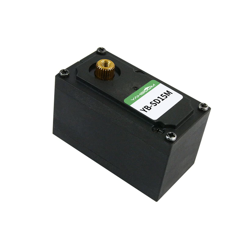
Additionally I did a bit of research into serial bus servos in general, as I didn’t even know they existed, and found that there are quite a few manufacturers for very different price points. On the more premium side there is DYNAMIXEL from ROBOTIS. And on the cheaper side there are quite a few chinese manufactures like Hiwonder, Waveshare, Yahboom and LOBOT. Looking at the available information for each, specially at the serial protocols used, it becomes clear that there is NO universal protocol and all of them use a DIFFERENT protocol, and different to the one I found on Gitee (for the Xaobao Serial Servo).
Serial Interface Protocol
As the Gitee Repository Serial Servo is the one that matched my servo the best, based on the available images, I started by using the information from this repository to try to communicate with my servo. It turns out this was the correct choice and it worked! Starting from the base interface settings, the serial interface settings, the baudrate used is 115200 and it uses the standard 8-N-1 UART configuration:
- Baud rate: 115200bps
- Data Size: 8-Bits
- Parity: None
- Stop bits: 1 bit
- Flow Control: None
The big difference between the serial interface used by the servo and a traditional UART is the use of only 1 data line, shared for both TX and RX, to send and receive data from/to the servo. The servo multiplexes/switches the data line between TX and RX tasks (TDM - Time Division Multiplexing), with the use of a dual bus buffer with 3-state outputs, the SN74LVC2G125DCUR. The servo is normally in listening, RX, mode waiting for data from the host e.g. a PC. This means that communications are initiated by the host. After a packet/command has been received by the servo, sent from the host, the target servo (based on the Device ID field in the packet) will switch to TX mode and answer to the command. The host itself must therefore switch to listening, RX, mode after a packet/command has been sent. Because multiple servos can be daisychained and then use the same 1 data line to communicate, all of them receive all the packets. To target, send, a packet to a specific servo, the packet/command has a Device ID field to identify the target servo. Only the target servo, with the matching Device ID, will execute the command and answer. It is therefore essential that ALL servos on the same data line use a unique Device ID.
There are a few different options to implement the TX/RX line multiplexing on the host side. The easiest is to just buy, or make, a board that does this. There are quite a few boards that can be purchased on AliExpress as almost all the serial bus servos use the same multiplexed single data wire interface. Alternatively, a simpler and faster way is to just ignore the returned packets from the servos and connect the single wire serial interface of the servo to a UART (or FTDI) TX line, with a 10k Ohm resistor in series to not burn either the UART transceiver or the servo transceiver when the servo switches to TX mode. This was the option I used to test the servo and works well to at least control the servos angle position.
With the hardware interface figured out it is time to look at the software/protocol side. Again, based on the same Gitee repository, and after using Google Translator to translate the available PDF documents, I was able to gather that the command packets from the host to the servo consist of 10 bytes with the following meaning:
| Byte # | 0 | 1 | 2 | 3 | 4 | 5 | 6 | 7 | 8 | 9 |
|---|---|---|---|---|---|---|---|---|---|---|
| Meaning: | Header MSB | Header LSB | Device ID | Command ID | Param 1 MSB | Param 1 LSB | Param 2 MSB | Param 2 LSB | Checksum | End Flag |
The first two bytes are the header bytes, and there are two kind of headers depending on the command type. For normal control commands, the header bytes are 0xFA 0xAF, while for firmware related commands the header bytes are 0xFC 0xCF. For both command types the end flag is the same, 0xED. The checksum field is simply the sum of bytes 2 to 7, e.g. from Device ID to Param 2 LSB, including both. The target servo is selected by the Device ID field, with 0x00 reserved as the broadcast (to all servos) address. The Command ID field identifies the command to be executed and is followed by 4 argument bytes, the parameter fields. See the table below for all the available commands (I have only tested the Set Angle command for now) and the respective parameter field values. The top part of the table are the normal commands, which use the 0xFA 0xAF header, while the bottom two are for the firmware related commands, which use the 0xFC 0xCF header.
| Command | Command ID | Param 1 MSB | Param 1 LSB | Param 2 MSB | Param 2 LSB |
|---|---|---|---|---|---|
| Set Angle | 0x01 | Angle (deg) | Speed (x20 ms) | Lock Time MSB (x20 ms) | Lock Time LSB (x20 ms) |
| Get Angle | 0x02 | Do not Care | Do not Care | Do not Care | Do not Care |
| LED Contr. | 0x04 | 0: OFF; 1: ON | 0x00 | 0x00 | 0x00 |
| Set Device ID | 0xCD | 0x00 | 0x00 | 0x00 | 0x00 |
| Set Angle Corr. | 0xD2 | Fw. Off. MSB | Fw. Off. LSB | Bw. Off. MSB | Bw. Off. LSB |
| Get Angle Corr. | 0xD4 | Do not Care | Do not Care | Do not Care | Do not Care |
| Get FW Version | 0x01 | 0x00 | 0x00 | 0x00 | 0x00 |
| Update Firmware | 0x02 |
Every command is answered by the target servo, with the answer depending on the command issued. See the table below to see the respective answer for each of the commands from the table above (I have not verified any of these yet as I ignored the answers):
| Command | State | Param 1 MSB | Param 1 LSB | Param 2 MSB | Param 2 LSB |
|---|---|---|---|---|---|
| Set Angle | Good: 0xAA; Error: 0xEE | Device ID | NA | NA | NA |
| Get Angle | Good: 0xAA; Error: 0xEE | Angle (deg) | Speed (x20 ms) | Lock Time MSB (x20 ms) | Lock Time LSB (x20 ms) |
| LED Contr. | Good: 0xAA; Error: 0xEE | Device ID | NA | NA | NA |
| Set Device ID | Good: 0xAA; Error: 0xEE | 0x00 | Old Device ID | 0x00 | 0x00 |
| Set Angle Corr. | Good: 0xAA; Error: 0xEE | 0x00 | 0x00 | 0x00 | 0x00 |
| Get Angle Corr. | Good: 0xAA; Error: 0xEE | Fw. Off. MSB | Fw. Off. LSB | Bw. Off. MSB | Bw. Off. LSB |
| Get FW Version | Good: 0xAA; Error: 0xEE | Version Nr. 1 | Version Nr. 2 | Version Nr. 3 | Version Nr. 4 |
| Update Firmware |
To communicate with the servo, as already mentioned above, I used a simple USB FTDI with the TX line connected through a 10 kOhm resistor to the servo data line. The servo is powered from a bench power supply with 7V, the servo must be supplied with voltages between 6V and 8.5V. On the PC I then wrote a simple Python script to assemble the necessary packet and send a Set Angle command to the servo, using the broadcast Device ID (0x00) as I have no idea what the Device ID of my servo is. For this Set Angle command, the first parameter sets the target angle of the servo in degrees (absolute values) while the second parameter sets the speed, the time it takes to reach that target angle in 20ms increments with 0 being the fastest. To note here that the speed is limited by the supply voltage to the servo, with higher voltages faster speeds can be achieved and with voltages close to the minimum of 6V the servo often stales when trying to reach higher speed and therefore a supply voltage of over 7V is recommended. This worked very well, with the probed servo data lines signal (in green from the input connector and in red from the output connector, daisy chain connector to next servo) shown in the figure below:
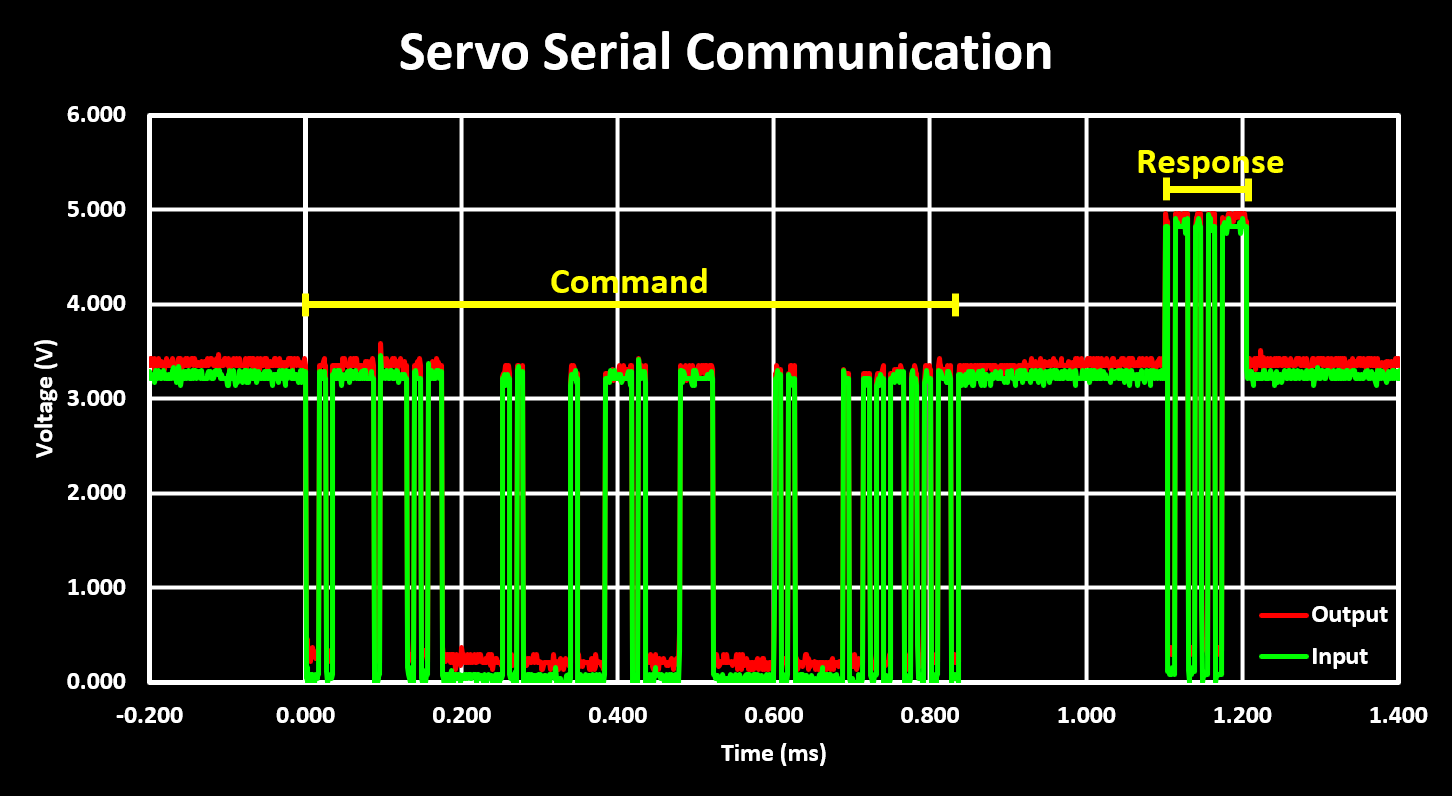
In this figure, the first packet visible is the command packet sent from the host (a PC through the USB FTDI) to the servo, the Set Angle command consisting of 10 bytes and with 3.3V logic levels. The second, and much smaller, packet is the answer from the servo, on the same line, consisting of only 2 bytes and with 5V logic levels. From this we get that the delay, and therefore time to switch from RX to TX, or TX to RX on the host side, is around 300 ms.
The developed and used Python code is available for download below.
Code: serialBusServo_Test.py