
Normal radios are designed to transmit audio and voice signals, not digital signals. Therefore to use these radios to transmit digital messages the digital information (bits) have to be encoded into an audio message that can be transmitted by those radios. This is where AFSK comes in. AFSK stands for Audio Frequency-Shift Keying and it encodes the digital bits into two audio tones, a space tone that typically encodes the ‘0’ bit and a mark tone that typically encodes the ‘1’ bit.
AFSK is popular amongst Radio Amateurs and is used for the for the Automatic Packet Reporting System (APRS). It was also used in early telephone-line modems. Almost all AFSK modems these days follow the Bell 202 specification. Bell 202 enables a half-duplex communication at 1200 bit/s, using a mark tone (‘1’ bit) of 1200 Hz and a Space tone (‘0’ bit) of 2200 Hz.
The basic set-up for AFSK transmission is shown in the block diagram below.

When transmitting AFSK over a radio, like in a radio amateur set-up, the AFSK modulation is done by a TNC (terminal node controller). The TNC is also responsible for packet/frame assembly. The computer communicates the data to transmit to the TNC over a USB or a RS-232 interface. The TNC takes the raw data, assembles it into a frame, typically is a AX.25 frame, and encodes and modulates the frame into the audio band using AFSK. The resulting audio signal is then input into a Radio which in turn FM modulates the audio signal into the RF band, normally either VHF or UHF, which is transmitted over air.
Reception is done in reverse order, the Radio demodulates the RF signal and feeds the resulting audio tone into the TNC which demodulates the audio signal, decodes the bits, de-assembles the packets and transmits the received data to the PC.
This means that when AFSK is transmitted by a Radio the bits are double modulated, first in the Audio band by the TNC and then FM modulated into the RF band by the Radio, and can therefore be called a FM-AFSK modulation. This chain of modulations can be seen in the block diagram below, where the red block is done in the TNC and the blue, orange and purple blocks are done in the Radio.

The pre-emphasis filter is commonly used when transmitting audio signals. It boosts higher frequencies to offset increased losses/attenuation of higher frequencies, improving SNR and therefore the audio quality. Most Radios apply this filter to the audio input to improve the clarity of the transmitted audio signal. The pre-emphasis filter in Radios have a time constant of 75 uS and a gain of 6 dB per octave.
The typical modulation used by the Radios is a narrowband FM modulation (bandwidth of 12.5 kHz) using a frequency deviation of 3000 Hz and transmitted in either the amateur VHF (144-148 MHz) or UHF (420-450 MHz) bands.
In this section I’ll explain how FM-AFSK can be implemented digitally. I use Scilab for this and the implementation can be used as a starting point for a C implementation to run on a MCU. The code can be used in part, as the basis for a TNC and feed into a Radio or in complete where the signal only needs to be feed to a mixer and up-converted to the desired frequency.
AFSK Modulation
The first step is implementing the AFSK modulation. This seems to be trivial as it is only encoding ‘0’ as a 2200 Hz tone and ‘1’ as a 1200 Hz tone and this can be done by simply switching between two sine waves with the desired frequencies, a basic FSK modulation, like in the code below:
function y = audioFSK(bitstream)
    bitrate = 1200;
    fMark = 1200;
    fSpace = 2200;
    index = 1;
    for i = 1:length(bitstream)
        for j = 1:(samplingFreq/bitrate)
            if bitstream(i) == 1
               y(index) =  sin(2*%pi*j*(fMark/samplingFreq));
               index = index + 1;
            else
               y(index) =  sin(2*%pi*j*(fSpace/samplingFreq));
               index = index + 1;
            end
        end
    end;
endfunction
The “samplingFreq” is how many points should be generated for each “second”. So for a bitrate of 1200 for each bit the code generates $ samplingFreq \over 1200 $ points of a sign wave with either a frequency of 1200 or 2200 Hz. The resulting signal in the time domain is shown in the figure below in Red with the corresponding bitstream in Green.
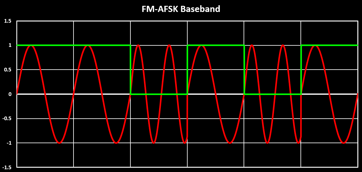
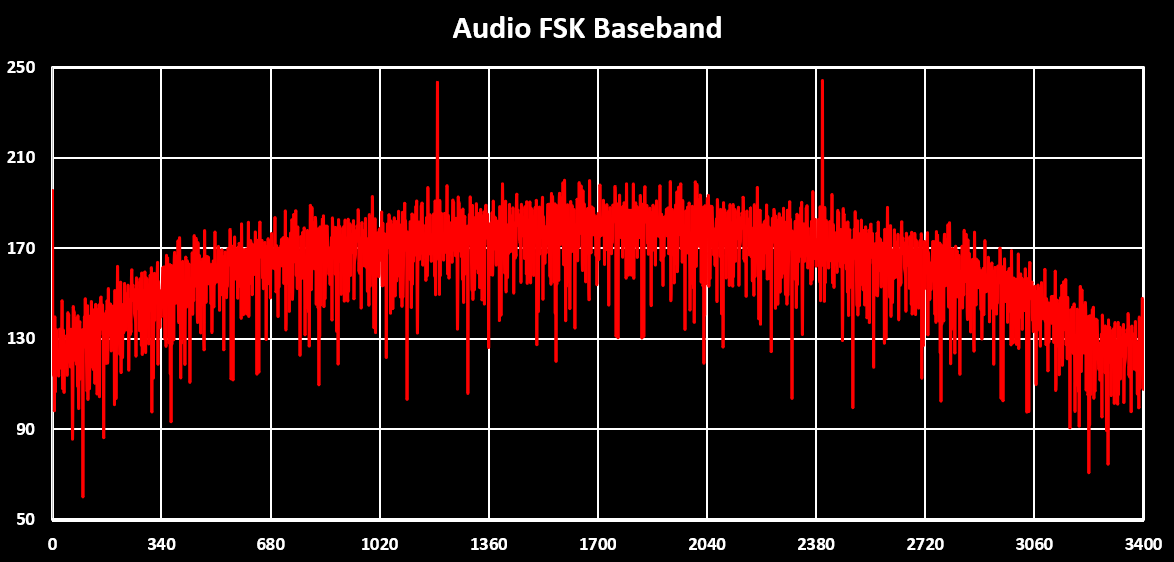
In this figure some hard transitions are visible when switching frequencies, illustrating a problem with this implementation. This happens because the frequencies used to modulate the bits, mark and space frequency, are not a multiple of the bitrate, the 2200 Hz is the problem, and therefore when transitioning between bits the phase of the two signals are not aligned. Phase discontinuities are undesirable because they generate a very wide spectrum, shown in the figure below.
To fix this, and decreasing the bandwidth of the signal, a continuous phase has to be achieved. This is done using a Continuos Phase Modulation, CPM or CPFSK. For this, first how the frequencies are generated has to be changed. Instead of generating two separate sine waves for the mark frequency and the space frequency a center frequency is used, $ F_C $, of 1700 Hz and the mark and space frequency are generated by adding deviation of +500 or -500 Hz to the $F_C$. This means that the bitstream needs to be encoded into a so called Non-Return-to-Zero (NRZ) signal, $ m(t) $, where the ‘0’ bit (space frequency) is encoded as a 1 and the ‘1’ bit (mark frequency) as a -1.
Next the $ m(t) $ signal, the modulating signal, has to be transformed into a continuous signal with no discontinuities to get a continuous phase. This is done by integrating the $ m(t) $ signal over time. An integral over any finitely valued function (which m(t) is assumed to be) will not contain any discontinuities.
The combination of these changes results in the following equation describing the modulation, where the lower limit of the integral, $ -\infty $, changes to 0 for a causal signal which $ m(t) $ is:
$$ s(t) = cos\left(2{\pi}F_{c}t - 2{\pi}{\Delta}F\int_{-\infty}^{t}m(\alpha)d\alpha\right) $$
For the integral the trapezoidal rule is used to calculate it in discrete time which is described in the following formula with N equally spaced panels/slices:
$$ \int_a^bf(x)dx \approx {{\Delta}x \over 2} \sum_{i=1}^N (f(x_{i-1}) + f(x_i)) $$
With this the function that generates a continuous AFSK signal in Scilab is the following:
function y = audioCPFSK(bitstream)
    fCenter = 1700;
    fDelta = 500;
    bitrate = 1200;
    bitstream = bitstream * 2 - 1; //Convert to NRZ
    steps = (samplingFreq/bitrate);
    y(1) = 0;
    m = 0;
    for i = 2:length(bitstream)*steps
        //"Interpolate" the bitstream to steps points per bit
        index = ceil(i/steps);
        indexPrev = ceil((i - 1)/steps);
        //Integration of the bitstream with trapezoidal rule
        m = m + ((bitstream(indexPrev) + bitstream(index))/2);
        //"FM" Modulation
        y(i) =  cos(2*%pi*i*(fCenter/samplingFreq) - 2*%pi*m*(fDelta/samplingFreq));
    end;
endfunction
The resulting signal in the time domain is shown in the figure below in Red with the corresponding bitstream in Green.
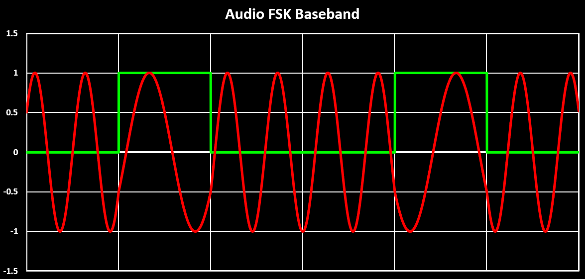
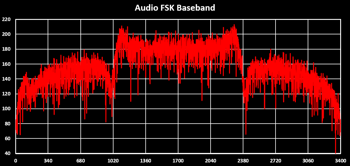
This figure clearly shows that the transitions are now much more smoother with no more phase discontinuities when switching frequencies, which results in a narrower spectrum of the signal as can be seen in the figure below:
This completes the AFSK part of the FM-AFSK modulation. This is the modulation done in a TNC with the resulting audio wave being injected into a Radio.
Pre-Emphasis
As seen in the beginning, a audio signal input into a Radio is emphasized by a pre-emphasis filter. The pre-emphasis filter is originally an analog first order high-pass filter, like in the figure below, with a time constant of 75 uS and a gain of 6 dB per octave. This is equivalent to having a low cut-off frequency of 2120 Hz and a gain of 20 dB/decade. They often also have an upper cut-off frequency outside the audio band, at around 30 kHz.
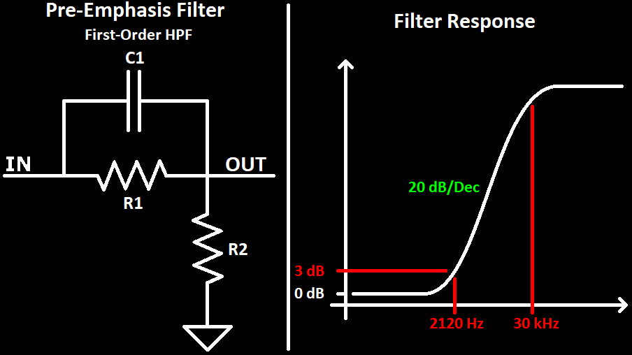
Based on this, the transfer function of the pre-emphasis filter can be calculated. Knowing that a pole introduces a gain of -20 dB/decade and a zero a gain of 20 dB/decade, the above filter has a zero at 2120 Hz and a pole at ~30 kHz which results in the following transfer function:
$$ H(s) = {{s + 2{\pi}2120} \over {s + 2{\pi}30000}} $$
To implement this filter in the digital domain, the pole can be ignored, as it is outside of the frequency range used and often even above the Nyquist limit, $ F_{S} \over 2 $. This results in a single zero filter, which can be implemented by a first order FIR filter with the following difference equation:
$$ y(n) = b_0x(n)+b_1x(n-1) $$
Where the value of the coefficients are $ b_0=1 $ and $ b_1=e^{-2*{\pi}*F_C*{1 \over F_{S}}} $, with $ F_{C} = 2120$ and $ F_S $ being the sampling frequency. The implementation of this filter, in Scilab, is visible below:
function y = Emphasis(signal)
    fc = 2120;
    a = exp(-2*%pi*fc*1/samplingFreq);  //Calculate Filter coefficient
    g = 50;                             //Gain to scale output to ~[-1;1]
    y(1) = 0;
    for i = 2:length(signal)
       //FIR HPF
       y(i) = (signal(i) - a*signal(i-1));
       y(i) = g*y(i);
    end
endfunction
With this the higher frequencies of a signal are now boosted, emphasized, or better the lower frequencies are attenuated. This can be seen in the figure below, where in green is the AFSK signal without the emphasis filter and in red with the emphasis filter:
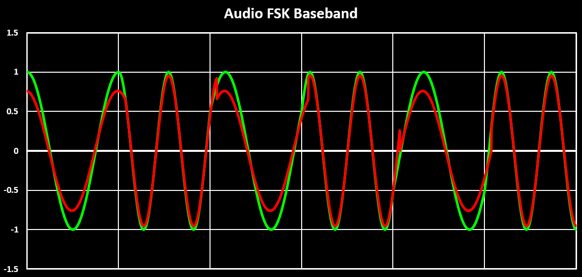
It is clearly visible that the higher frequency, 2200 Hz, has a higher amplitude in contrast to the lower one, 1200 Hz. There are also, again, some very harsh discontinuities visible, but in contrast to the ones seen when designing the AFSK modulator, these ones are due to amplitude and not phase discontinuities of the signal and therefore they don’t increase the signal bandwidth. This can be seen when looking at the spectrum of the emphasized signal, shown in the figure below. In green is the spectrum of the AFSK signal without the emphasis filter and in red with the emphasis filter:
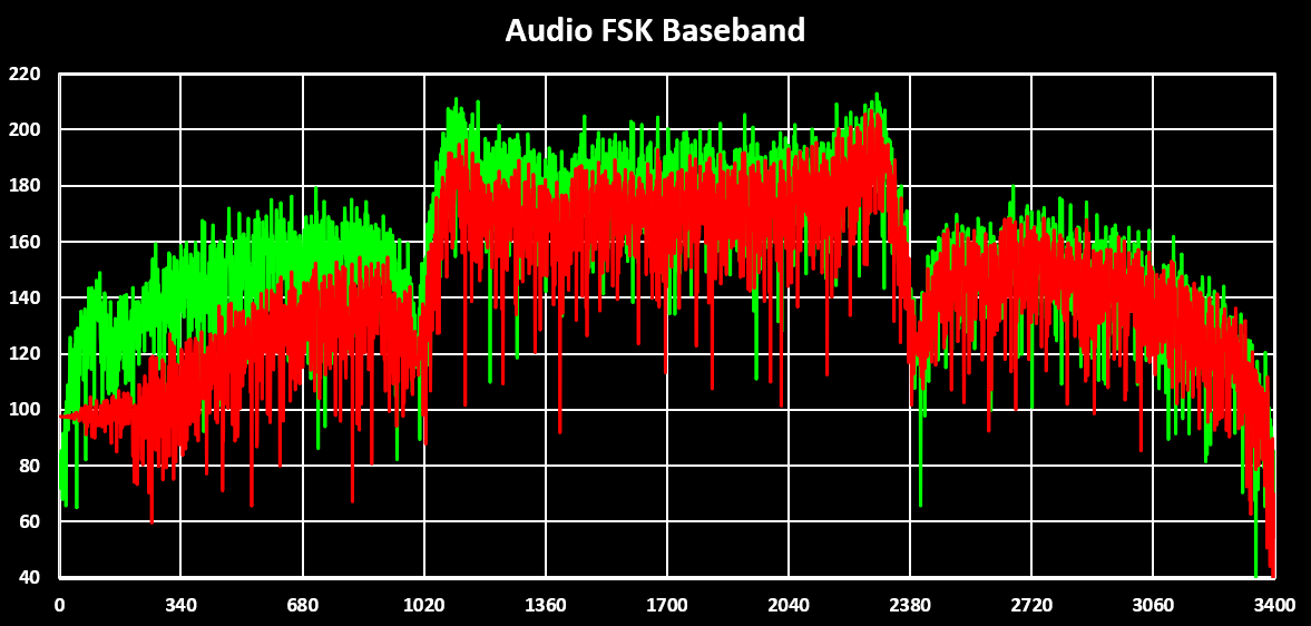
The spectrum also shows very well the boost of higher frequencies, or the attenuation of the lower frequencies, and that the signal bandwidth remained the same. This is the signal that is used in the next step, the FM modulation, to get the complete FM-AFSK modulation.
FM Modulation
The final step to get the FM-AFSK modulation is to implement the FM modulator. Because it is not practical to directly modulate the signal onto the carrier RF frequency a intermediate frequency (IF) is used. I used a IF frequency of 5200 Hz, this because it is the IF frequency used for the AFSK mode in my VUHFRadio. Another parameter is the frequency deviation, or modulation index, which for AFSK is 3000 Hz. When using a sinusoidal baseband signal, which AFSK is, the FM modulation is defined by the following function:
$$ y(t) = cos\left(2{\pi}F_ct + {{\Delta}F \over F_m}sin(2{\pi}f_xt) \right) $$
Where $ {\Delta}F $ is the frequency deviation, 3000 Hz, $ F_m $ is the maximum frequency of the baseband signal, 2200 Hz, $ F_c $ the carrier or intermediate frequency, 5200 Hz, and $ sin(2{\pi}f_xt) $ the baseband signal. This is implemented in Scilab using the code below, where $ sin(2{\pi}f_xt) $ is substituted with the AFSK baseband signal.
function y = FMModulation(baseband)
    fCenter = 5200;
    fDeviation = 3000;
    fMax = 2200;
    mIndex = (fDeviation/fMax);
    for i = 1:length(baseband)
        y(i) = cos(2*%pi*i*(fCenter/samplingFreq) + mIndex*baseband(i));
    end
endfunction
The output of this function is the FM-AFSK modulation and it’s time domain signal is visible in the figure below. In green is the baseband AFSK signal and orange the FM-AFSK signal.
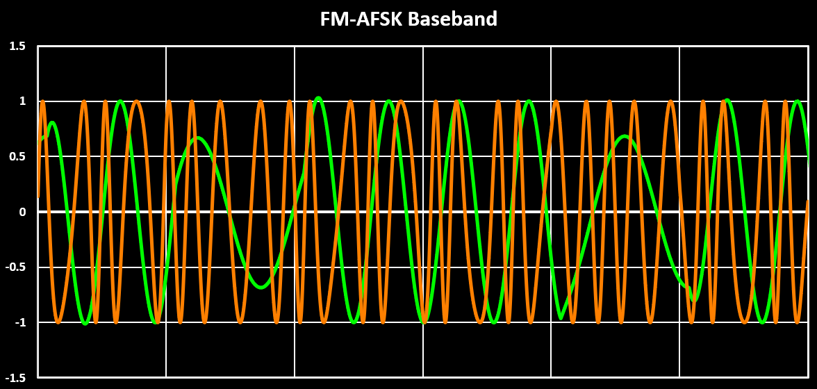
The corresponding spectrum of the FM-AFSK signal is visible in the figure below:
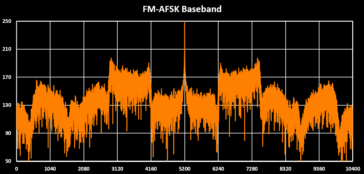
With this the digital implementation of the FM-AFSK modulation is completed. This can now be ported and optimized to run on a MCU, and by feeding the generated output into a Mixer it can be up-convert it to the desired RF frequency and transmitted over air.
Now that the modulation is implemented let’s see how FM-AFSK can be demodulated. The modulation part implemented before will be used to test and verify the demodulation code. Starting with an overview of the demodulation chain, as was done with the modulation, it is visible in the figure below that the chain has the same basic blocks as the modulation just in reverse order. As was the case with the modulation, the purple, orange and blue part is done in the Radio and the red in the TNC, when using HAM Radios.

As was the case with the modulation, the full processing chain outside the RF part i.e. after downconversion is implemented in digital using Scilab. This poses the first problem, it is common that the downconversion mixer is a quadrature mixer meaning that it outputs the downconverted (IF signal) in-phase (I) and in quadrature (Q), a 90° phase shift to the in-phase signal, simplifying and improving the performance of the demodulation stage. In this case, as the modulation code outputs the baseband (IF signal) with only the in-phase part, the quadrature component has to be calculated. This is done using the Hilbert Transform.
Hilbert Transform
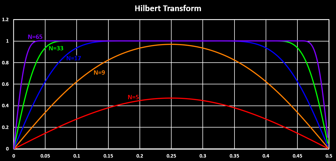
The Hilbert Transform is a operation that phase shifts a signal by 90°, which is what is needed to get the Q signal from only the I signal. One way to implement the Hilbert Transform is using a FIR filter with an odd number of coefficients (even order) and odd symmetry (antisymmetric), also known as a Type 3 FIR filter, which is the method used here. This results in a band-pass filter with a normalized band-pass bandwidth of around 0.95, this is $ BW = 0.95 { F_S\over2 } $.
The FIR filter block diagram used for the Hilbert Transform can be seen in the figure below, with the main difference to a normal FIR filter being the tap in the middle of the delay line for the I signal. This is because the FIR Hilbert Transform does not only shift the output signal by 90° but it is also delayed by half the delay line length, so the I signal also needs to be delayed the same amount. This is done by taping the middle of the delay line. In the block diagram $ Z^{-1} $ is a one sample delay and a[n] are the filter coefficients.

The Scilab implementation of this filter is shown below. The delay line is implemented with a circular buffer, dLine, where $ Z^{-1} $ is dLine[dLineIndex], $ Z^{-2} $ is dLine[dLineIndex - 1], $ Z^{-3} $ is dLine[dLineIndex - 2], and so on. The function takes an input signal and an array of the FIR coefficients.
function [i,q] = HilbertTransform(signal, a)
    dLine = [1: length(a)-1];
    dLineIndex = 0;
    for i = 1:length(signal)
        //Calculate index of the center of the delay line
        index = pmodulo(dLineIndex - (length(dLine) / 2), length(dLine)) + 1;
        i(i) = dLine(index);
        //FIR filter calculations
        q(i) = signal(i) * a(1);
        for j = 1:length(dLine)
            index = pmodulo(dLineIndex - j, length(dLine)) + 1;
            q(i) = q(i) + a(j+1) * dLine(index);
        end
        //"Shift" delay line samples
        dLineIndex = dLineIndex + 1;
        if dLineIndex > length(dLine) then
            dLineIndex = 1;
        end
        dLine(dLineIndex) = signal(i);
    end
endfunction
To calculate the FIR filter coefficients in Scilab, the function hilb() is used. The function takes as arguments the number of coefficients to be calculated and returned, the filter shaping type used, and additional filter shaping type parameters. For this example I used 65 coefficients and using a Kaiser-window with parameter set to 8. I used this because I read here that using a Kaiser-window with parameter 8 gives “pretty good” audio performance and we are working with an “audio” signal so why not. The Hilbert Transform FIR filter coefficients are therefore given by:
a = hilb(65, 'kr', 8);In the figure below the calculated coefficients for different filter lengths/order, number of coefficients is shown. The anti-symmetry is visible and also that the odd coefficients are always 0. This means that the implementation of the filter can be optimized a lot by ignoring the odd coefficients and by exploring the anti-symmetry.
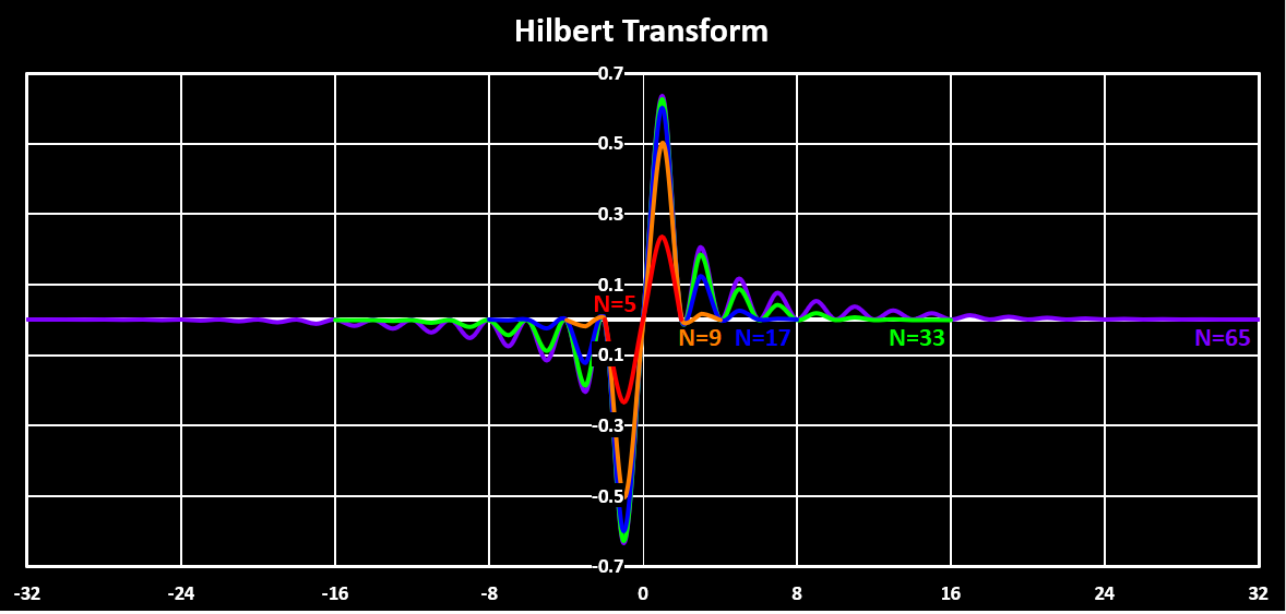
The figure below shows the resulting filter shapes when using those coefficients. It is visible that only a filter with an order greater then 16 has a unitary gain bass-band and that the normalized bandwidth of 0.95 is only achieved with an order greater then 64.
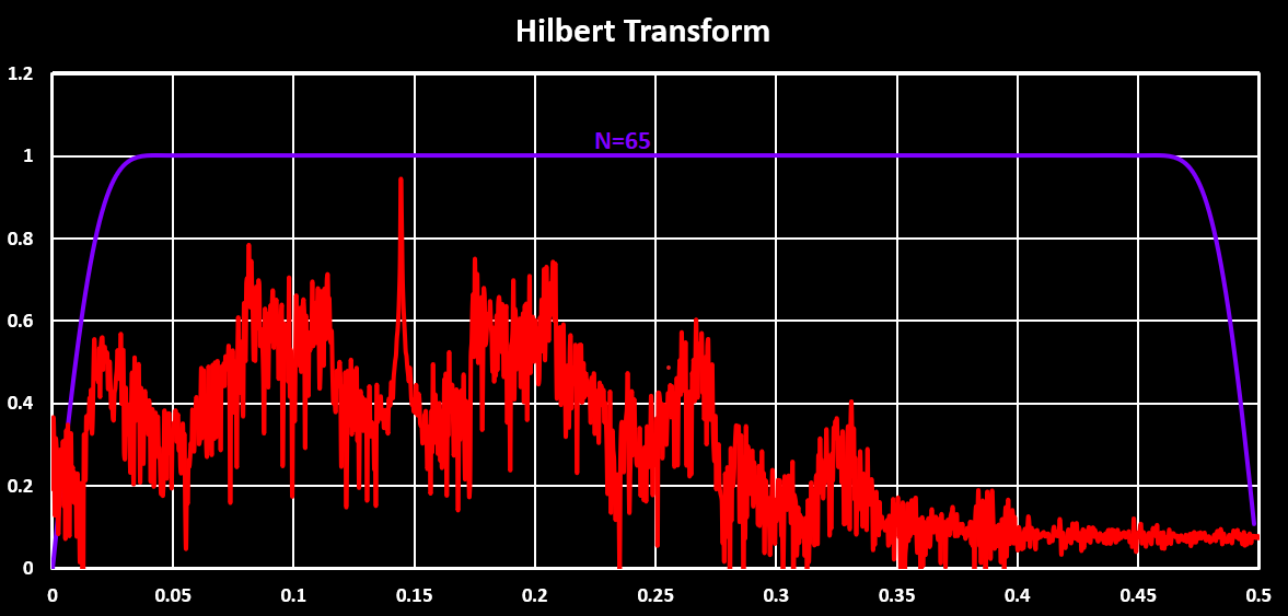
In order to not distort the baseband signal when passing through the Hilbert Transform FIR filter, the filter bandwidth needs to be large enough to include the whole baseband signal and ideally the baseband signal is centered around $ F_S\over4 $, 0.25, which is not always achievable or even desirable. In the figure below the spectrum of the baseband signal with the filter shape is visible, showing that it fits inside the filter bandwidth even though the center frequency of the baseband is not $ F_S\over4 $.
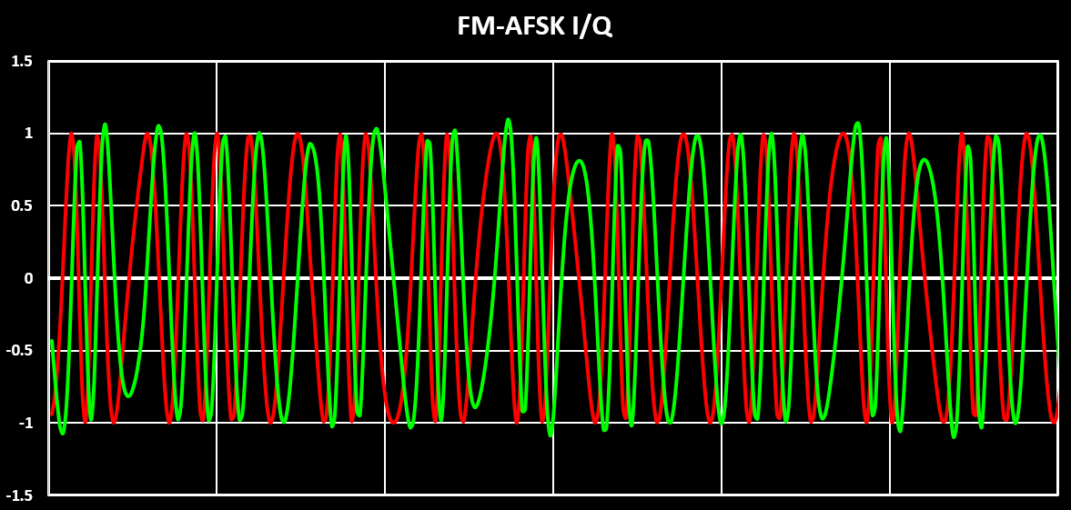
The output of the Hilbert Transform FIR Filter can be seen in the figure below. In red the I signal is shown, this is the baseband signal but delayed by half the filter delay line length, and in green the generated Q signal. It can be seen that the Q signal is indeed 90° offset in relation to the I signal. With this both I and Q signals are now present.
FM Demodulation
To demodulate a FM signal the frequency variation of the incoming signal has to be extracted. This can be done with many different techniques, maybe the most well known one is using a PLL where the control signal of the VCO is the demodulated signal, the frequency variation of the carrier wave. This type of demodulator is called coherent as it tracks the input signal and generates an error signal, the demodulated signal. This type was not used here due to higher complexity.
The other type of FM demodulators used are non-coherent ones, for example quadrature demodulators, the ones used here. Quadrature demodulators, sometimes also called arctan demodulator or differentiation demodulator, use I and Q data of the modulated baseband signal to extract the frequency variation. These demodulators extract the frequency variation in two stages. First the phase information of the signal is extracted and by derivation of the the phase signal over time, the frequency change over time is obtained.
The quadrature signals can be seen as the real (I) and imaginary (Q) component of the signal. With this in mind, and recording how the phase of a imaginary number is calculated, the instantaneous phase of the signal is given by $ \theta = arctan \left( Q \over I \right) $. And by applying the derivation over time to this, the frequency variation is obtained, $ f = {d \over dt} arctan \left( Q \over I \right) dt $. This is the demodulation represented in the block diagram of the full demodulation chain.
By taking into account that in a discrete signal the derivate is simply the difference between the current sample and the previous one, $ {dx(n) \over dt} = x(n) - x(n-1) $. And using the subtraction rule of $ arctan $ functions, $ arctan(x) - arctan(y) = arctan \left( {x-y} \over {1+xy} \right) $, the above equation can be written as:
$$ f(n) = \theta(n) - \theta(n-1) = arctan \left( {Q(n)I(n-1) - I(n)Q(n-1)} \over {Q(n)Q(n-1) + I(n)I(n-1)} \right) $$
This is the equation used to demodulate the FM signal and the implementation in Scilab is shown below:
function y = FMDemodulation(signalQ, signalI)
    iDelayLine = 0;
    qDelayLine = 0;
    y(1) = 0;
    for i = 2:length(signalQ)
        //Im(Sn)*Re(Sn+1) - Re(Sn)*Im(Sn+1)
        numerator = signalQ(i)*iDelayLine - signalI(i)*qDelayLine;
        //Re(Sn)*Re(Sn+1) + Im(Sn)*Im(Sn+1)
        denominator = signalQ(i)*qDelayLine + signalI(i)*iDelayLine;
        //Like atan2 in C
        y(i) = atan(numerator, denominator);
        //One Sample delay line
        iDelayLine = signalI(i);
        qDelayLine = signalQ(i);
    end
endfunction
There is another form of the arctan demodulation that is used, and is also implemented here. This second version is obtained by calculating the derivative of the $ arctan $ function, $ {d \over dt} arctan(x) = { 1 \over 1 + x^2 } $, but because x in this case is a function this is:
$$ {d \over dt} arctan(f(x)) = { 1 \over 1 + x^2 } {df(x) \over dt} $$
Because $ f(x) $ is actually $ Q(x) \over I(x) $, the quotient rule of the derivative can be used:
$$ {d {Q(x) \over I(x)} \over dt} = { I(x){dQ(x) \over dt} - Q(x){dI(x) \over dt} \over I(x)^2 } $$
Now by using this result in the previous equation and by multiplying everything by $ I(x) $ to simplify the equation, the final equation is obtained:
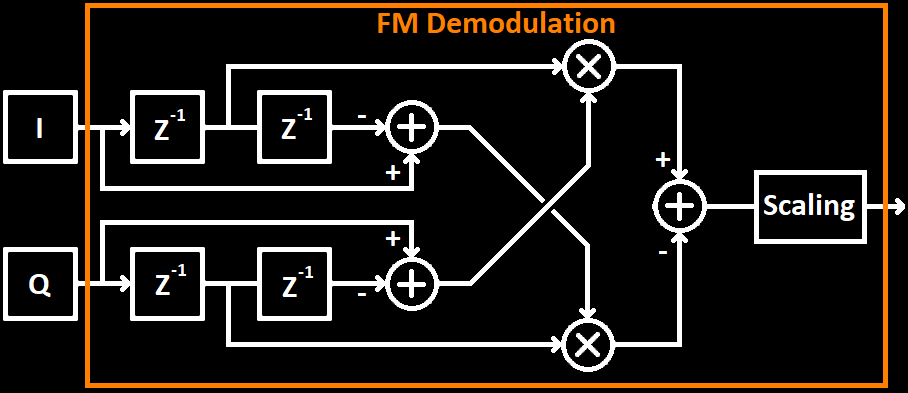
$$ f(x) = \Delta \theta(x) = { I(x){dQ(x) \over dt} - Q(x){dI(x) \over dt} \over {I(x)^2 + Q(x)^2} } $$
In discrete time the simplified block diagram of this equation is shown below:
And the corresponding Scilab implementation is the following:
function y = FMDemodulation2(signalQ, signalI)
    iDelayLine = [0,0];
    qDelayLine = [0,0];
    for i = 1:length(signalQ)
        //Calculate delta values,
        dI = signalI(i) - iDelayLine(2);
        dQ = signalQ(i) - qDelayLine(2);
        //Multiplication part
        mI = iDelayLine(1) * dQ;
        mQ = qDelayLine(1) * dI;
        //Possible Scaling
//        mA = 1 / (signalI(i)*signalI(i) + signalQ(i)*signalQ(i));
        mA = 1;
        y(i) = mA * (mI - mQ);
        //Shift delay line samples
        iDelayLine(2) = iDelayLine(1);
        iDelayLine(1) = signalI(i);
        qDelayLine(2) = qDelayLine(1);
        qDelayLine(1) = signalQ(i);
    end
endfunction
Using I and Q signals generated via the Hilbert Transform in the FM demodulation stage, the demodulated signal is obtained and shown in the figure below. The first implementation is depicted in red, and the second in green.
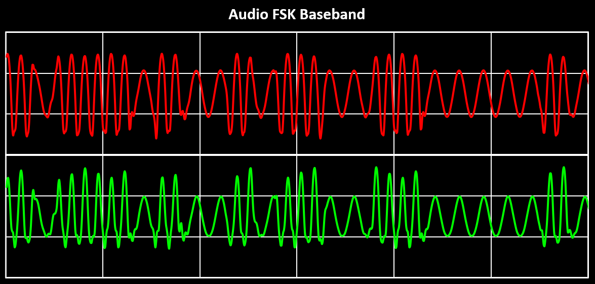
The first thing that stands out is the attenuation of lower frequencies compared to higher ones. This indicates that both FM demodulators exhibit high-pass filter characteristics. Since no pre-emphasis filter was used in the original modulated signal, the observed low-frequency attenuation is only from the FM demodulation process. If pre-emphasis had been used, this attenuation would be even greater. The figure also reveals that the first demodulator (red) generates a slightly less distorted signal and is therefore used subsequent processing steps.
A known issue with these types of FM demodulation, particularly those relying on derivation and the arctangent function, is their sensitivity to DC offsets between the I and Q baseband signals. In the software-based examples above, this issue does not occur because all signals ideal. However, in practical implementations, DC offsets between I and Q can introduce significant distortion in the demodulated signal. To demonstrate this effect, a DC offset was introduced to the Hilbert Transform generated I and Q signals ($I = I + 0.1$ and $Q = Q - 0.1$), and then they are feed to the FM Demodulator. This results is shown in blue in the figure below. For comparison, the red trace shows the output without any DC offset.
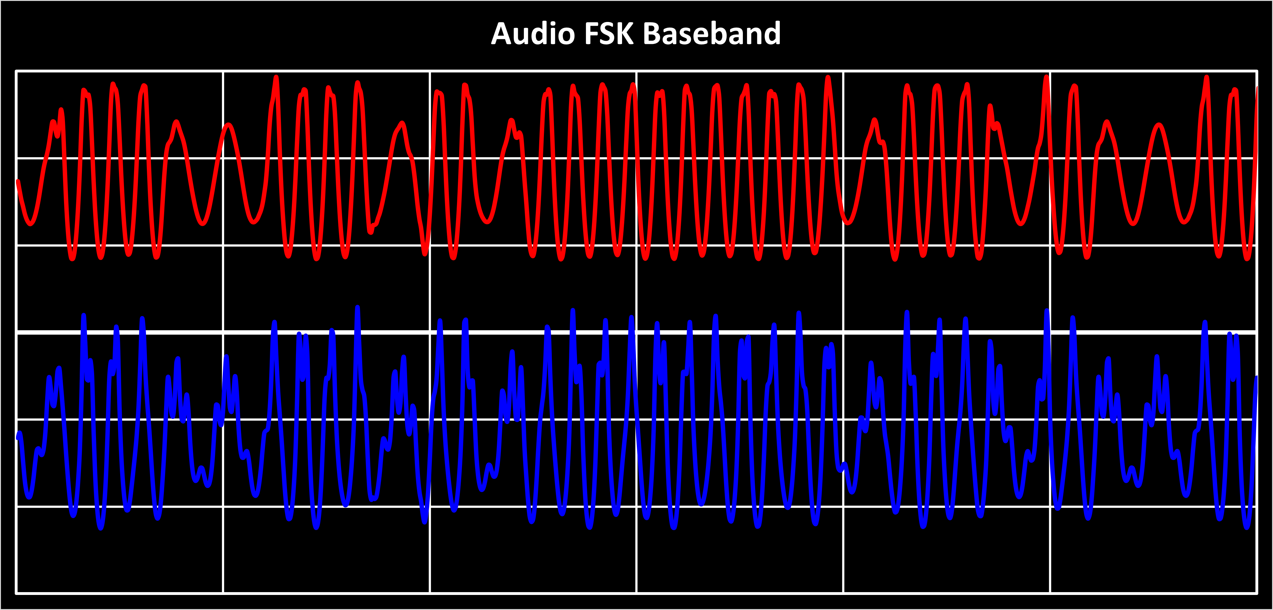
Even this moderate offset, approximately 10% of the signal amplitude, produces a visible distortion. The effect becomes even more evident when demodulating an unmodulated input signal (i.e., a zero array fed to the FM modulator). The result is shown shown below, again in red without a DC offset and in blue with a DC offset.
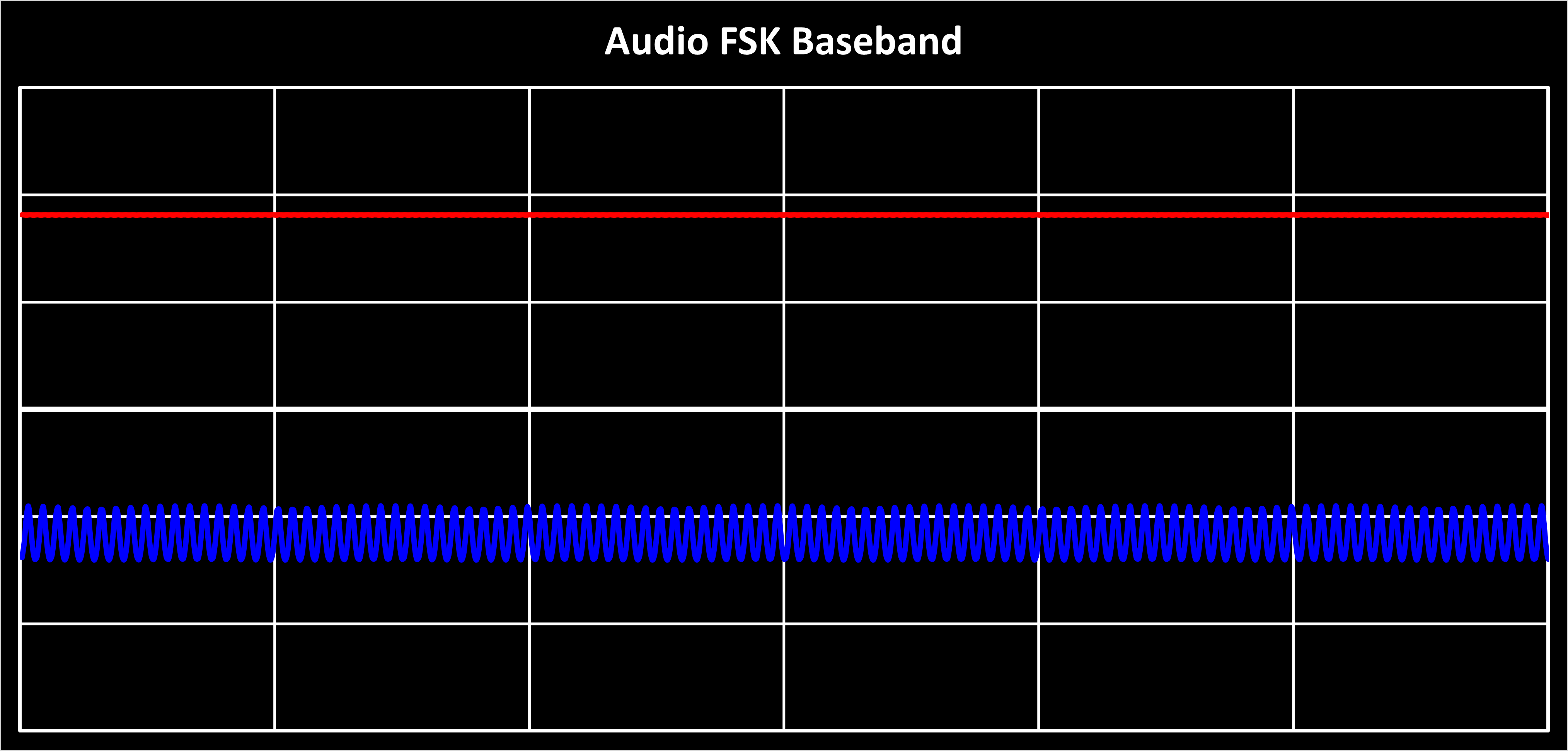
Ideally, an unmodulated FM signal should demodulate to a flat DC level, proportional to the carrier frequency. However, due to the DC offset, a pronounced ripple appears. This ripple has the same frequency as the baseband carrier frequency. This issue is especially problematic in zero-IF receivers, which often use DC-coupled I/Q paths between the baseband mixer and ADC inputs.These ripples correspond to the frequency difference between the transmitter and receiver RF frequencies, manifesting as a very low-frequency carrier in baseband. To mitigate this issue, it is essential to either implement a precise DC offset compensation or adding a digital DC blocker (i.e., a very low-frequency high-pass filter) before the FM demodulation stage.
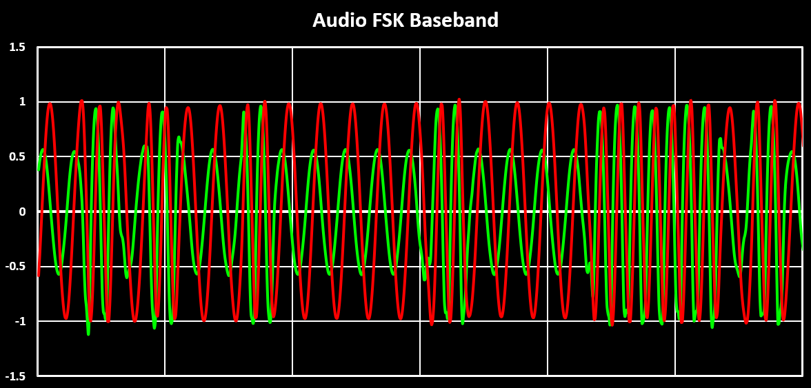
Additionally, to compensate for the intrinsic high-pass behavior and recover the low frequency components, a first-order low-pass filter can be used. Its cutoff frequency should be at least one decade lower than the lowest frequency of interest, in this case this is 1200 Hz. This filter is similar to the de-emphasis filter stage, which will be detailed in the next section. The only difference is the cutoff frequency used here is lower, around 100 Hz. The result of using this compensation filter is shown in the figure below where the original FM demodulated signal is shown in green and the same signal after the high-pass filter is shown in red.
De-Emphasis
The next step is to implement the de-emphasis filter, the “inverse” of the pre-emphasis filter. This will remove the emphasis of the higher frequencies generated by the pre-emphasis filter in the modulator/transmitter. As with the pre-emphasis filter, the de-emphasis filter is implemented in the radios as a first order analog filter. The de-emphasis filter, being the opposite of the pre-emphasis filter, is a high-pass filter with the same low cut-off frequency (2120 Hz), high cut-off frequency (30 kHz) and gain (20 dB/decade) as the pre-emphasis filter. The de-emphasis filter is represented in the figure below.
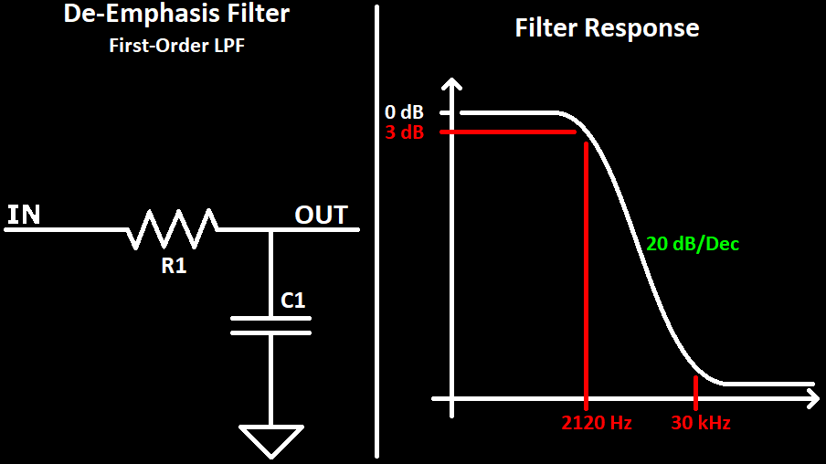
The transfer function of the de-emphasis filter is also just the inverse of the pre-emphasis filter:
$$ H(s) = {{s + 2{\pi}30000} \over {s + 2{\pi}2120}} $$
The de-emphasis filter can be implemented in the digital domain as a first order IIR filter. This time the zero can be ignored, creating a single pole filter with the following difference equation:
$$ y(n) = b_0x(n)+a_1y(i-1) $$
Where the value of the coefficients are $ b_0=(1-a_1) $ and $ a_1=e^{-2*{\pi}*F_C*{1 \over F_{S}}} $, with $ F_{C} = 2120$ and $ F_S $ being the sampling frequency. The implementation of this filter, in Scilab, is visible below:
function y = DeEmphasis(signal)
    fc = 2120;
    a = exp(-2*%pi*fc*1/samplingFreq);  //Calculate Filter coefficient
    g = 1; //Gain to scale output to ~[-1;1]
    y(1) = signal(1);
    for i = 2:length(signal)
       //IIR LPF
       y(i) = ((1-a)*signal(i) + a*y(i-1));
       y(i) = g*y(i);
    end
endfunction
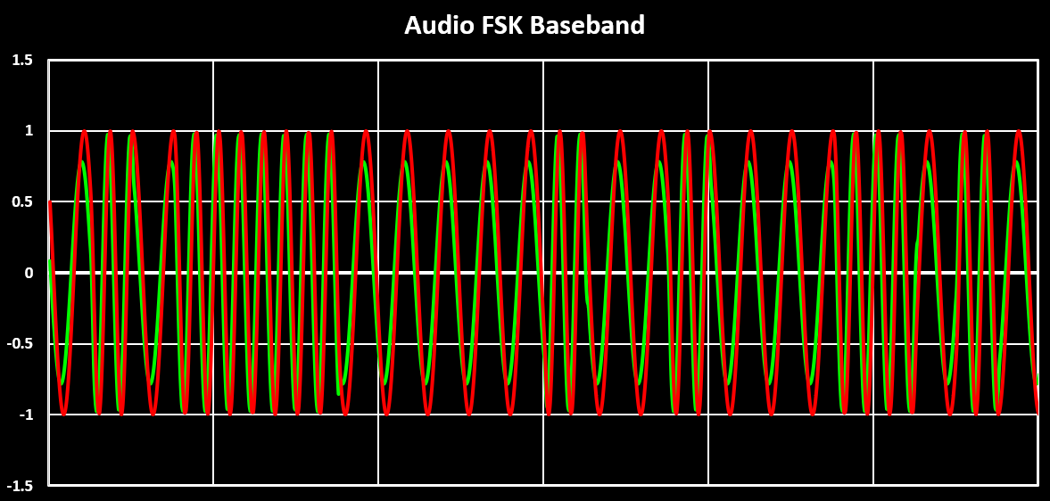
To test the implemented de-emphasis filter, the output of the pre-emphasis filter is feed into it and the output has to return to the initial from. The result of this is shown in the figure below. In green is the output of the pre-emphasis filter, with the lower frequencies attenuated, and in red the output of the de-emphasis filter, with all frequencies having the same amplitude again.
AFSK Demodulation
After de-emphasis, or if the audio signal comes from a HAM Radio, the audio signal is now demodulated so that the transmitted bits can be retrieved. The AFSK demodulation is just a FSK demodulation, and as with the FM demodulation can be done in a coherent way or in a non-coherent way. Here, as with the FM demodulation, only non-coherent methods are used. It is also possible to use the same demodulation methods used for FM demodulation, with some post processing, but there are more efficient demodulations available. Also the FM demodulations implemented here both relied on quadrature data and therefore a Hilbert Transform which is computationally expensive and in the FSK case not necessary.
Two different non-coherent non-quadrature FSK demodulations will be presented and implemented. The first one is the normal example of a FSK non-coherent demodulation where the two frequencies that encode the bits, space and mark frequencies, are band-pass filtered and analyzed. The analysis of the band-passed signals is done by an envelop detector of the filtered signals and then comparing both envelops to detect which bit value was transmitted. This is the method displayed in the FM-AFSK demodulation block diagram.
For this implementation, first the two band-pass filters have to be designed and implemented. For this a FIR filter can be used with the band-pass center frequency being the mark/space frequency and with a bandwidth such that the other frequency is attenuated significantly. As an example here a FIR filter with 17 coefficients is used, with a bandwidth of 400 Hz for each frequency. The two filter shapes are visible in the figure below, with the AFSK spectrum as a reference to see that the center frequencies of both filters are correct.
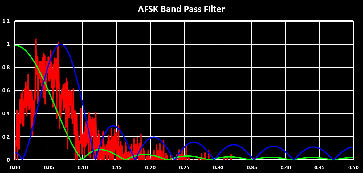
Although it may seem that the filters are not very well centered, specially the mark frequency one, they are good enough and represent a good compromise between selectivity and computational requirement. Something I also noticed is that if the number of coefficients of the FIR filter is much larger then $ {F_{Mark/Space} \over F_{S}} $ the band-pass FIR filters don’t work as intended. I guess that this has to due with delay introduced by the filters.
The implementation of this FSK demodulator in Scilab is shown below. The FIRFilter function is basically the same as the Hilbert Transform function, and the coefficients are calculated by the ffilt function. The envelope detection can be done in many ways, here a square-law envelope detector is implemented, this is very similar to a diode and capacitor circuit in the analog domain. The signal is squared and then low-pass filtered. The low-pass filter is implemented the same way as the de-emphasis filter, but with a cut-off frequency of 1000 Hz, slightly below the bit-rate. Finally the decision is done by simply subtracting the output of the space frequency arm from the mark frequency arm.
function y = FSKDemodulation(signal)
    //Space and Mark frequency BPF
    space = FIRFilter(baseband, ffilt("bp", 17, 2000/samplingFreq, 2400/samplingFreq));
    mark = FIRFilter(baseband, ffilt("bp", 17, 1000/samplingFreq, 1400/samplingFreq));
    //Space and Mark Envelope Detection
    spaceEnvelope = LPF(space^2, 1000);
    markEnvelope = LPF(mark^2, 1000);
    y = markEnvelope - spaceEnvelope;
endfunction
The other FSK demodulator implemented is the cross-correlation demodulation. In this the mark and space frequencies are “filtered” by using correlation with a locally generated mark and space frequency. For each frequency a correlation block is used, this could be expanded to any number of additional frequencies and can therefore also be used for 4-FSK or 8-FSK modulations. The correlation is done by multiplying the modulated signal by locally generated in-phase and in quadrature (sine and cosine) signal with the frequency of the signal that should be “filtered”, in this case the mark or space frequency. The result of this is then integrated over one bit period, squared and summed. The output of all correlations are then input into a decision block which decides which bit (or symbol) was transmitted. The block diagram of this demodulator is shown in the figure below:
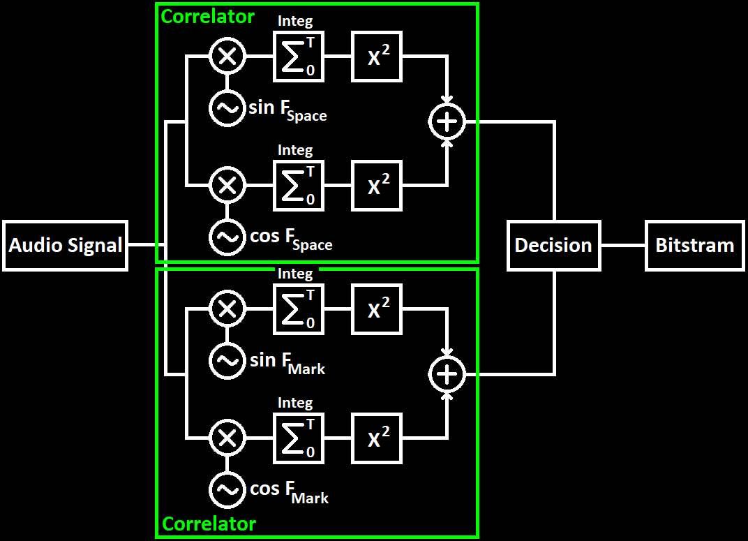
The digital implementation of this demodulator is straight forward. The integration part is the sum of the N previous samples, with N being the number of samples in a bit period, $ F_{bitrate} \over F_{S} $. The decision is done by subtracting the output of the space frequency arm from the mark frequency arm. The Scilab implementation of this demodulator is shown below:
function y = FSKDemodulation2(signal)
    fMark = 1200;
    fSpace = 2200;
    for i = 1:length(signal)
       markI(i) = signal(i) * sin(2*%pi*i*(fMark/samplingFreq));
       markQ(i) = signal(i) * cos(2*%pi*i*(fMark/samplingFreq));
       spaceI(i) = signal(i) * sin(2*%pi*i*(fSpace/samplingFreq));
       spaceQ(i) = signal(i) * cos(2*%pi*i*(fSpace/samplingFreq));
       //Integration over bit period, samplingFreq/1200
       markIInteg = 0;
       markQInteg = 0;
       spaceIInteg = 0;
       spaceQInteg = 0;
       for j = 0:(samplingFreq/1200 - 1)
           if (i-j) > 0 then
               markIInteg = markIInteg + markI(i-j);
               markQInteg = markQInteg + markQ(i-j);
               spaceIInteg = spaceIInteg + spaceI(i-j);
               spaceQInteg = spaceQInteg + spaceQ(i-j);
           else
               markIInteg = markIInteg;
               markQInteg = markQInteg;
               spaceIInteg = spaceIInteg;
               spaceQInteg = spaceQInteg;
           end
       end
       s1 = markIInteg*markIInteg + markQInteg*markQInteg;
       s2 = spaceIInteg*spaceIInteg + spaceQInteg*spaceQInteg;
       y(i) = s1 - s2;
    end
endfunction
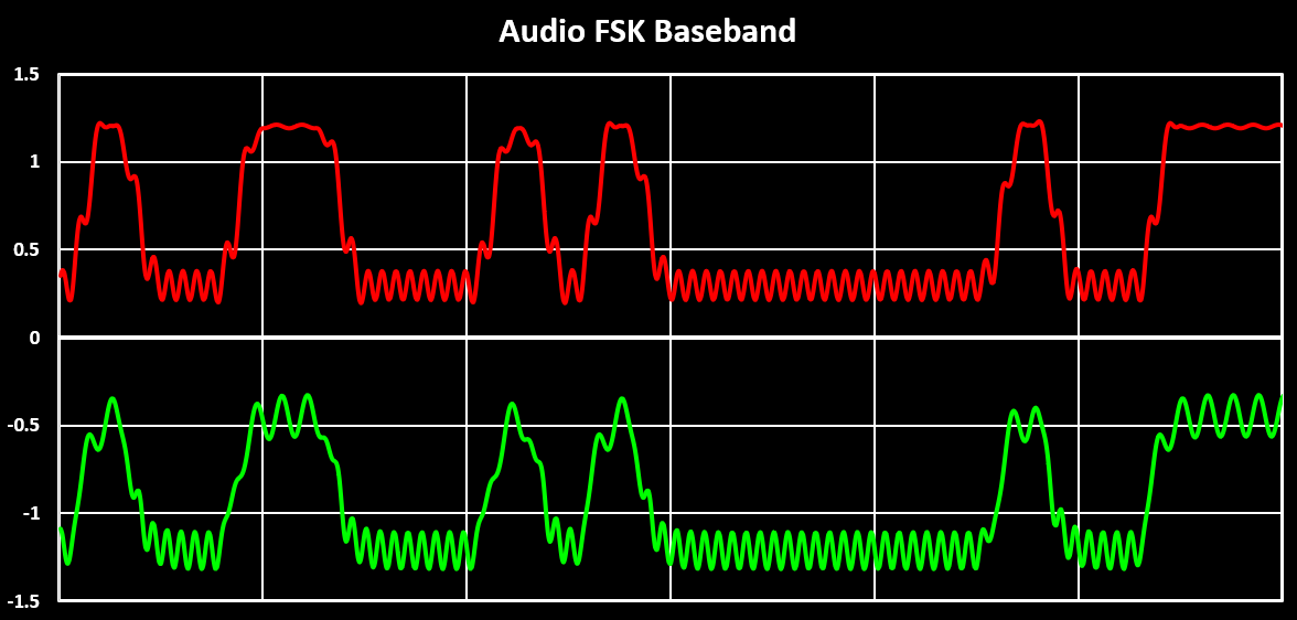
The (normalized) demodulated signal output for each of the two demodulators is visible in the figure below. In red the output of the cross-corelation implementation is shown and in green the output of the band-pass filter implementation is shown. The results look similar but it can be seen that the cross-corelation demodulation outputs a more well defined signal. It is also less computationally intensive then the band-pass filter demodulation as that one uses two high order FIR filers which are computationally intensive.
The final step is recovering the bit clock and extracting the information bits.
The final step is now to recover the transmitted bitstream which involves both bit clock recovery and bit decision. One of the simplest methods for this is using a numerically controlled oscillator (NCO), a counter operating at the sampling rate. The NCO counts up to a maximum value of $ ncoMax = F_{S} \over F_{bitrate} $ at which point the NCO is reset. The bit decision is made at the midpoint of this counter, when $ nco = {1 \over 2} {F_{S} \over F_{bitrate}} $. This ensures that bit sampling occurs at the center of the bit period, where the demodulated is typically most stable and least likely to be in transition.
To synchronize the NCO with the incoming signal, edge detection is used on the demodulated waveform. In its simplest form, this uses a threshold with hysteresis. A rising edge is detected when the signal crosses above a level defined as $th + hyst$, and a falling edge when it drops below $th - hyst$. When an edge is detected, the NCO is reset, realigning the bit clock with signal transitions. Below is a Scilab implementation showing this basic bit and bit clock recovery mechanism:
function [bit, clk] = BitRecovery(signal)
    bitrate = 1200;
    nco = 0;
    ncoMax = round(samplingFreq / bitrate);
    th = 0;
    thHyst = 50;
    bLast = 0;
    currentBit = 0;
    currentBitClk = 0;
    bit(1) = 0;
    clk(1) = 0;
    for i = 1:length(signal)
        //Edge detector
        if bLast == 0 & signal(i) > (th + thHyst) then
            //Positive edge detected
            bLast = 1;
            nco = 0;
            currentBitClk = 1;
        elseif bLast == 1 & signal(i) < (th - thHyst) then
            //Negative edge detected
            bLast = 0;
            nco = 0;
            currentBitClk = 1;
        end
        nco = nco + 1;
        //Bit decission
        if nco == round(ncoMax / 2) then
            if signal(i) > th then
                currentBit = 1;
            elseif signal(i) < th then
                currentBit = 0;
            end
            currentBitClk = 0;
        elseif nco >= ncoMax then
            nco = 0;
            currentBitClk = 1;
        end
        //Bit and Bit Clock at sample rate, not bit rate here
        bit(i) = currentBit;
        clk(i) = currentBitClk;
    end
endfunction
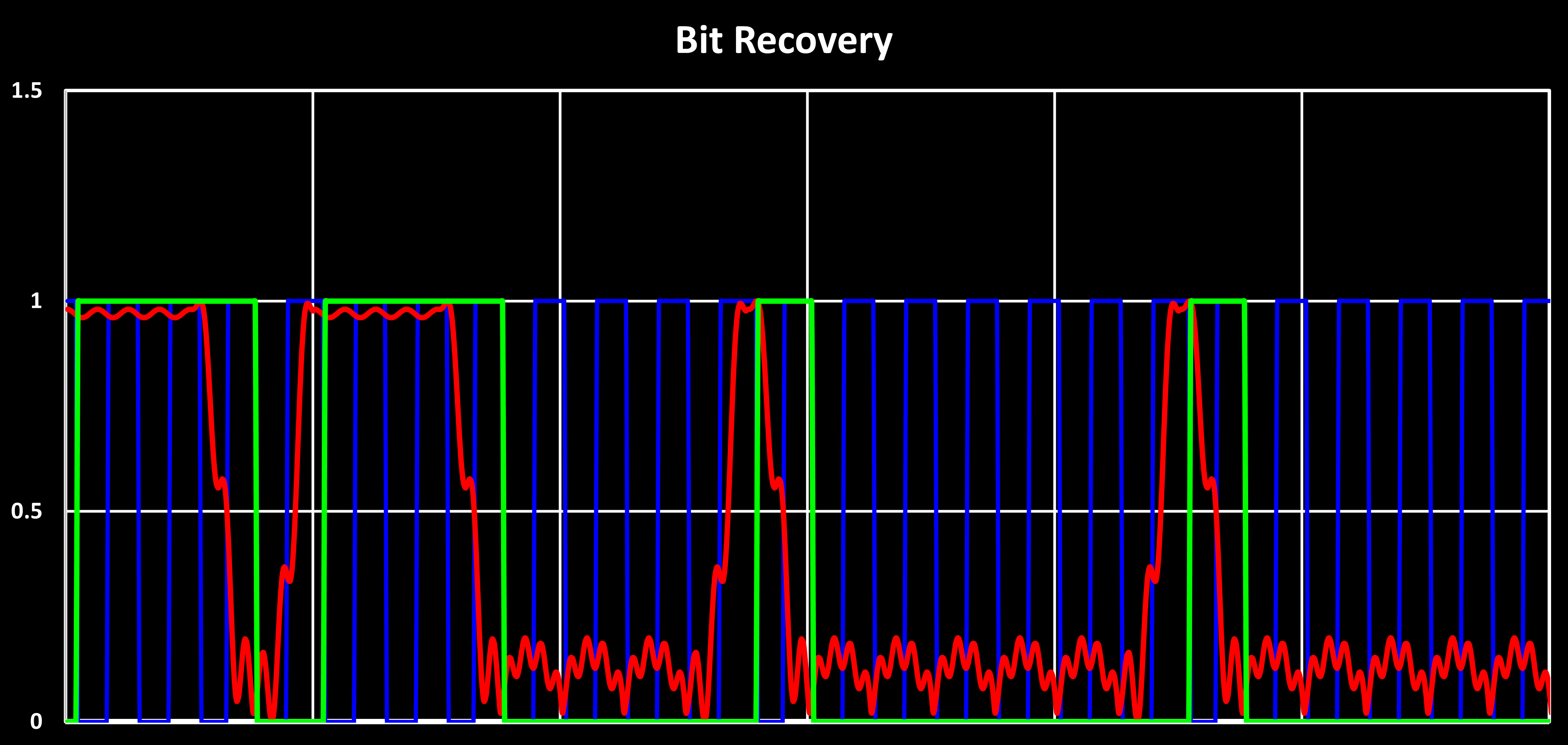
Feeding the demodulated signal obtained in the previous step, with the cross-corelation FSK demodulator, to the bit recovery function yields the signals shown in the figure below. In red is the demodulated signal, in green is the recovered binary bitstream, in blue the recovered bit clock, and the orange line marks the thresholds levels used for edge detection. This shows that even a simple implementation of bit recovery can work quite well, especially in low-noise environments like the one shown here.
In practical applications, however, several factors can complicate bit recovery. One issue is when the transmitted bit sequences has few transitions or edges, such as during long sequences of identical bits. This is often addressed on the transmitter side by using differential encoding and bit stuffing to guarantee periodic transitions, or with scrambling to produce a more randomized bit pattern. Another challenge occurs when the distinction between the signal levels representing the two bit values is weak. Here, the bit recovery can be optimized by using a more complex bit clock recovery where the NCO’s increment dynamically using a feedback mechanism, and by oversampling and averaging across multiple samples per bit rather than relying on a single sample.