
Micro-ROS is a open-source framework developed to get ROS 2 features to resource constrained Microcontrollers (MCU), as stated in the official documentation: “Micro-ROS is a robotic framework bridging the gap between resource-constrained microcontroller and larger processors in robotic applications that are based on the Robot Operating System”. It started being developed as the Ofera (Open Framefwork for Embedded Robotics Application) Project funded by the EU (under European Union’s Horizon 2020) and bringing together companies from different countries: Bosch, Fiware, PIAP, Acutronic Robotics and eProsima. Micro-ROS is fully open-source, with the source code available on GitHub, under the same license model as ROS.
In a sense, Micro-ROS is an improved, ROS 2 compatible, replacement for rosserial, a protocol wrapping ROS 1 messages in a way to easily transmit them over e.g. a serial connection and be read/written from a MCU. Micro-ROS is more feature rich then rosserial, providing more then just a wrapper for ROS 2 messages and other ROS 2 feature to MCUs. But, for most use cases, Micro-ROS is only used to read/write (subscribe/publish) ROS 2 messages between a MCU and the ROS 2 host (agent). Micro-ROS is also not standalone, it requires a ROS 2 instance running the Micro-ROS agent (broker) to manage the communications from the Micro-ROS client. In this, Micro-ROS running on the MCU is always the client and never the server, with communications between two clients having to pass through the host e.g. there are no direct communications between two MCUs running Micro-ROS. This is a big limitation, and work is being done in solving this with a Peer-to-Peer communication option. A full list of implemented features from ROS 2 in Micro-ROS can be found here.
Micro-ROS architecture
Micro-ROS tries to reuse as much of the ROS 2 client cod, from the “rcl” library, as possible but with changes to alleviate dynamic memory requirements, using static memory allocation whenever possible, creating the optimized “rclc” library. The underlying communication standard is DDS, the same used by ROS 2, but with a special optimized, for resource constrained MCUs, implementation from eProsima called Micro-XRCE-DDS. Also, Micro-ROS was developed with RTOS in mind, specifically FreeRTOS and Zephyr, but the use of those specific RTOS’s, or a RTOS at all, is not a requirement.
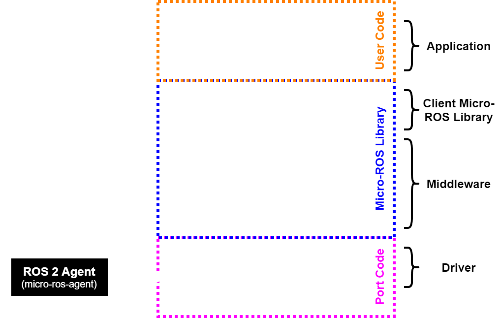
In essence, a complete Micro-ROS project will consists of 4 parts, as shown in the figure below:
- The Micro-ROS static library: Contains all the Micro-ROS code and API as well as the DDS communication middleware (shown in blue in the figure).
- The Micro-ROS agent: The Micro-ROS broker running on the host PC under a ROS 2 environment (shown on the left in the figure).
- The MCU specific port code: The base transport layer code and functions as well as time reference (shown in purple in the figure).
- THe Micro-ROS client application: The actual user application that will Micro-ROS, to subscribe and publish ROS 2 messages/topics (shown in orange in the figure).
This section will give instructions, from scratch, on how to port Micro-ROS to “any” MCU and independent of the IDE, not using any specific IDE or IDE plugin. The instructions are based on my experience, and struggles, in getting Micro-ROS ported and running, without the use of plugins and/or pre-built/configured projects, on two different boards and MCUs: a custom board using the STM32H723 and the RT-Thread HMI-Board. The instructions shows the full process, starting at setting up the build environment, going through building the static Micro-ROS library and finally integrating it into the MCU, with a custom transport layer, giving insides and important details on the way based on challenges that I encountered on my own journey.
The process of porting Micro-ROS to a new MCU can be split into four steps:
- Step 1: Toolchain setup e.g. installing ROS 2 and required dependencies and packages
- Step 2: Build of the Micro-ROS static library (firmware)
- Step 3: Integration of the Micro-ROS static library into the MCU environment and project
- Step 4: Creation of port specific functions for the transport layer and time reference.
Step 1: Toolchain setup
The first step is to install ROS 2, in my case this was ROS 2 Humble Hawksbill on Ubuntu 22.04 LTS. I highly recommend using Linux for ROS 2 and to build the Micro-ROS static library, with Windows there are many additional challenges that will appear. After building the Micro-ROS library it can then be used in any IDE even under Windows without any problems. This is also what I did, built the Micro-ROS library in Ubuntu and then developed the MCU code with an IDE in Windows. The full instructions on how to install ROS 2 Humble on Ubuntu can be found in the official ROS documentation. Just follow those instructions and try running some examples to verify the correct installation and setup of ROS 2.
After the successful installation of ROS 2, some additional packages must be installed. These packages are required to built custom ROS 2 packages like Micro-ROS. The instructions for this can be found here but essentially the following two bash command must be executed:
sudo apt install python3-colcon-common-extensions
sudo apt-get install python3-pip
This finishes the software prerequisites to being able to build Micro-ROS. The next step is to set-up a Micro-ROS workspace, the folder where the package will be built. The instructions for this can be found in the official Micro-ROS documentation. To create a new Micro-ROS workspace, call the following bash commands:
# Source ROS 2 (Humble)
source /opt/ros/humble/setup.bash

# Create the Micro-ROS workspace and get set-up code
mkdir microros_ws
cd microros_ws
mkdir src
git clone -b humble https://github.com/micro-ROS/micro_ros_setup.git src/micro_ros_setup

# Possible to require update of dependencies using rosdep
sudo apt update && rosdep update
rosdep install --from-paths src --ignore-src -y

# Build the Micro-ROS tools and source them
colcon build
source install/local_setup.bash
After this, we now have a fully prepared built environment to build our Micro-ROS static library.
Step 2: Build Micro-ROS static library (firmware)
In this step we will built the Micro-ROS static library with custom options and for our desired MCU. The instructions for this can be found in the official Micro-ROS documentation. The first step is to navigate to the Micro-ROS workspace folder, created in the previous step, and open a terminal in the workspace root folder. From the terminal source both ROS 2 Humble and the local package, using the bash commands shown below. If the terminal from the previous step was not closed then this can be skipped.
# Go to the Micro-ROS workspace folder
cd microros_ws

# Source ROS 2
source /opt/ros/humble/setup.bash

# Source local packages
source install/local_setup.bash
To create the basic Micro-ROS static library (firmware) build environment, a simple ROS 2 package script must be run:
ros2 run micro_ros_setup create_firmware_ws.sh generate_libThis creates all the necessary folders, gets the source files, prepares make files etc… At the end of this, we only have to add/create two files: the toolchain configuration and Micro-ROS library configuration files that we will call “my_custom_toolchain.cmake” and “my_custom_colcon.meta” respectively. These files can be created with the files explorer or with the bash commands below:
touch my_custom_toolchain.cmake
touch my_custom_colcon.meta
The created files are empty and have to be filled with the correct configurations. Basic example configuration and structure can be found in the Micro-ROS documentation. I’ll show here the content of the files I used for the STM32H723. The first file is the toolchain configuration file, for the case of the STM32H723 this file should read:
set(CMAKE_SYSTEM_NAME Generic)
set(CMAKE_CROSSCOMPILING 1)
set(CMAKE_TRY_COMPILE_TARGET_TYPE STATIC_LIBRARY)
# SET HERE THE PATH TO YOUR C99 AND C++ COMPILERS
set(CMAKE_C_COMPILER arm-none-eabi-gcc)
set(CMAKE_CXX_COMPILER arm-none-eabi-g++)
set(CMAKE_C_COMPILER_WORKS 1 CACHE INTERNAL "")
set(CMAKE_CXX_COMPILER_WORKS 1 CACHE INTERNAL "")
# SET HERE YOUR BUILDING FLAGS
set(FLAGS "-O2 -mfloat-abi=hard -mfpu=fpv5-sp-d16 -fsingle-precision-constant -ffunction-sections -fdata-sections -fno-exceptions -mcpu=cortex-m7 -nostdlib -mthumb" CACHE STRING "" FORCE)
set(CMAKE_C_FLAGS_INIT "-std=c11 ${FLAGS} -DCLOCK_MONOTONIC=0 -D'__attribute__(x)='" CACHE STRING "" FORCE)
set(CMAKE_CXX_FLAGS_INIT "-std=c++14 ${FLAGS} -fno-rtti -DCLOCK_MONOTONIC=0 -D'__attribute__(x)='" CACHE STRING "" FORCE)
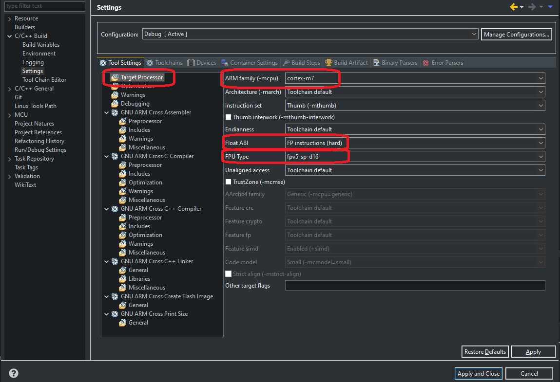
set(__BIG_ENDIAN__ 0)The first important setting is the used compiler, most basic IDEs will use the standard arm-none-eabi-gcc compilers just as set in the files above but for 0some IDEs this may have to be changed. Next are the compilation flags that are MCU specific, set under the line SET HERE YOUR BUILDING FLAGS. Starting by setting the desired FPU type, depending on if the MCU has hardware accelerated floating point, “-mfloat-abi=hard”, or not, “-mfloat-abi=soft”, and if yes what version/type of FPU. The version of the FPU depends on the MCU used with most Cortex-M7, like the STM32H723, using a generation 5 FPU and therefore the FPU flag is set as “-mfpu=fpv5-sp-d16”. In contrast, most Cortex-M4f MCUs, like the one used in the RT-Thread HMI-Board, use a 4th generation FPU and therefore the FPU flag is set to “-mfpu=fpv4-sp-d16”. The other important flag that has to adjusted for each MCU, is the flag specifying what MCU Core is used e.g. what ARM-Cortex core (M0, M3, M4, M7, etc…). For the STM32H723 using a ARM Cortex-M7 the flag is set to “-mcpu=cortex-m7” while for the HMI-Board using a ARM Cortex-M4f this flag is set to “-mcpu=cortex-m4”. All other flags can be left as is with most MCU builds. To make sure the build flags are correct/compatible with the MCU, they can be compared with the flags used/set in the IDE where the MCU project will be created (I used Eclipse), to note that the optimization flags can be different and can therefore ignored:
The other file created sets the Micro-ROS library configurations. To set the transport layer type, here we want a custom transport layer, the configuration “-DUCLIENT_PROFILE_CUSTOM_TRANSPORT=ON” is set to “ON” and the configuration “-DRMW_UXRCE_TRANSPORT=custom” is set to “custom”. The other interesting settings are under the “rmw_microxrcedds” section. Here we can set the maximum number of nodes (1), publisher (5), subscribers (5), services (1) and clients (1) that should be supported, as well as the maximum message history (4) used for a reliable QoC mode. A more detailed description of all settings under this section, can be found in the eProsima Micro XRCE-DDS GitHub. An example configuration, the one I used, is shown below:
{
    "names": {
        "tracetools": {
            "cmake-args": [
                "-DTRACETOOLS_DISABLED=ON",
                "-DTRACETOOLS_STATUS_CHECKING_TOOL=OFF"
            ]
        },
        "rosidl_typesupport": {
            "cmake-args": [
                "-DROSIDL_TYPESUPPORT_SINGLE_TYPESUPPORT=ON"
            ]
        },
        "rcl": {
            "cmake-args": [
                "-DBUILD_TESTING=OFF",
                "-DRCL_COMMAND_LINE_ENABLED=OFF",
                "-DRCL_LOGGING_ENABLED=OFF"
            ]
        },
        "rcutils": {
            "cmake-args": [
                "-DENABLE_TESTING=OFF",
                "-DRCUTILS_NO_FILESYSTEM=ON",
                "-DRCUTILS_NO_THREAD_SUPPORT=ON",
                "-DRCUTILS_NO_64_ATOMIC=ON",
                "-DRCUTILS_AVOID_DYNAMIC_ALLOCATION=ON"
            ]
        },
        "microxrcedds_client": {
            "cmake-args": [
                "-DUCLIENT_PIC=OFF",
                "-DUCLIENT_PROFILE_UDP=OFF",
                "-DUCLIENT_PROFILE_TCP=OFF",
                "-DUCLIENT_PROFILE_DISCOVERY=OFF",
                "-DUCLIENT_PROFILE_SERIAL=OFF",
                "-DUCLIENT_PROFILE_STREAM_FRAMING=ON",
                "-DUCLIENT_PROFILE_CUSTOM_TRANSPORT=ON"
            ]
        },
        "rmw_microxrcedds": {
            "cmake-args": [
                "-DRMW_UXRCE_MAX_NODES=1",
                "-DRMW_UXRCE_MAX_PUBLISHERS=5",
                "-DRMW_UXRCE_MAX_SUBSCRIPTIONS=5",
                "-DRMW_UXRCE_MAX_SERVICES=1",
                "-DRMW_UXRCE_MAX_CLIENTS=1",
                "-DRMW_UXRCE_MAX_HISTORY=4",
                "-DRMW_UXRCE_TRANSPORT=custom"
            ]
        }
    }
}
With the build environment created and both configuration files filled out, the Micro-ROS static library (firmware) can now be built with the bash command below:
ros2 run micro_ros_setup build_firmware.sh $(pwd)/my_custom_toolchain.cmake $(pwd)/my_custom_colcon.metaA common error that can happen during the build process, and that occurred to me, is micro-ROS: Could not find ROS middleware implementation ‘rmw_microxrcedds’. This error occurs when the installed and sourced ROS 2 instance uses a different DDS middleware, like eProsima Fast DDS (rmw_fastrtps_cpp) or Eclipse Cyclone DDS (rmw_cyclonedds_cpp), then the one required by Micro-ROS, eProsima Micro XRCE-DDS (rmw_microxrcedds). Instructions on how to change the used DDS middleware can be found in the official ROS 2 Documentation. To change the middleware to the correct one, to the one Micro-ROS uses, eProsima Micro XRCE-DDS, the environment variable “RMW_IMPLEMENTATION” must be changed by using the following bash command (Solution found in the ROS Forum):
export RMW_IMPLEMENTATION=rmw_microxrceddsThe build script compiled the Micro-ROS firmware for our specified target MCU (through the .cmake file) and with our specified Micro-ROS configuration (through the .meta file). The output is a library file, “libmicroros.a”, located in the “microros_ws/firmware/build” folder, as well as the header files (.h) located in the “microros_ws/firmware/build/include” folder. These are the files that have to be added and included in the MCU project. Normally the generated files and folder structure doesn’t need any modification, but for some reason it can happen that the header files folder have a nested structure (e.g. “include/action_msgs/action_msgs/”) that must be corrected, de-nested. This is done by copying, and after deleting, the nested folder content, e.g. “include/action_msgs/action_msgs/”, to the root folder, e.g. “include/action_msgs/”. I also found the recommendation to only copy the header files, “.h” files, and not the code files, “.c” files, so possibly erase all “.c” files but not the “.cpp”.
Step 3: Integrating Micro-ROS into MCU project
Now that the Micro-ROS library has been generated it can be included into our desired MCU project. The steps differ between the different IDEs but the general guide line is the same. Here I’ll use the example of integrating it into a Eclipse IDE Project (for ARM Cortex M embedded system), which should be fairly similar to other IDEs that are based on Eclipse like STM32CubeIDE (STMicroelectronics), Simplicity Studio (Silicon Labs), Code Composer (Texas Instruments) and the ESP-IDF Eclipse Plugin. These steps are the same steps required for integrating any kind of library, like the CMSIS-DSP library or for some pre-compiled RTOS:
-
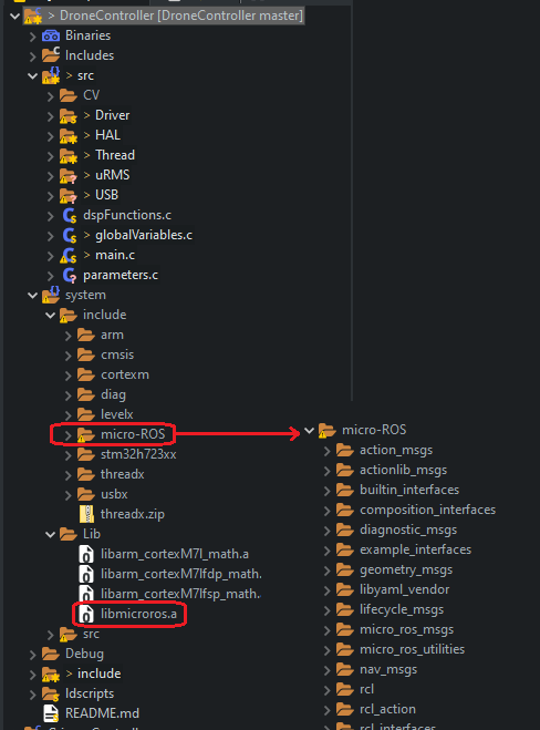
Step 1: Copy the library file to the MCU project folder, it doesn’t matter to much to where. For my Eclipse project I copied it to “system/Lib” where I already have the CMSIS-DSP library file. It is also possible (what some IDEs do) to create a folder for all Micro-ROS files and copy it to there e.g. with the Micro-ROS setup for STM32CubeIDE all generated files are located in “micro_ros_stm32cubemx_utils/microros_static_library_ide/libmicroros”.
-
Step 2: Copy the header files, the full content of the “microros_ws/firmware/build/include” folder, to the MCU project folder. For me I copied it to “system/include/micro-ROS” but again the organization depends on the MCU project and IDE e.g. with the Micro-ROS setup for STM32CubeIDE all generated files are located in “micro_ros_stm32cubemx_utils/microros_static_library_ide/libmicroros”.
After these two steps your project should have all the required files added, and should look something like this:
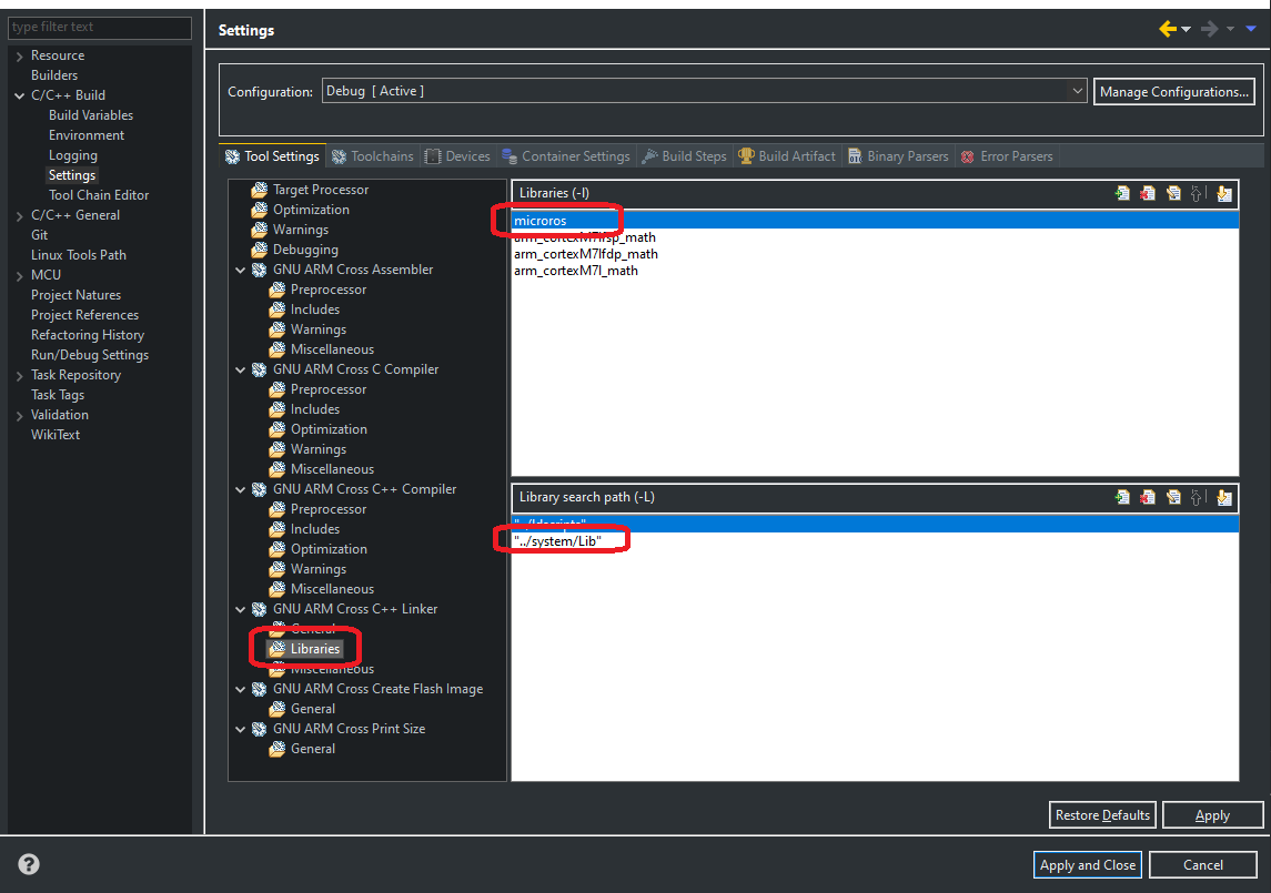
- Step 3: Add the library and the library path to the build linker. In case of Eclipse this is done in “Project Settings->C/C++ Build->Settings->Tool Settings->GNU ARM Cross C++ Linker->Libraries”, just like shown in the figure below:
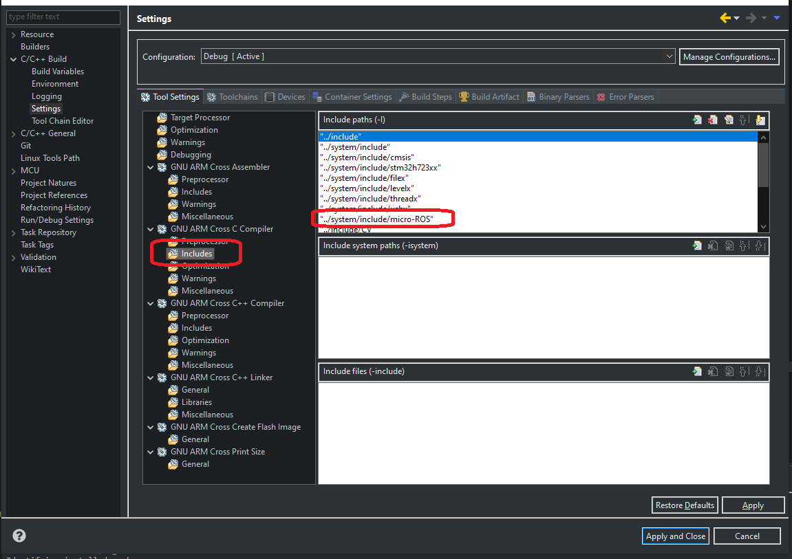
- Step 4: Finally add the folder containing the header files to the build include path. Again, in case of Eclipse this is done in the “Project Settings->C/C++ Build->Settings->Tool Settings->GNU ARM Cross C Compiler->Include paths”, just like shown in the figure below:
This concludes the integration of the generated Micro-ROS library into the MCU project. The next step is then to add the required MCU specific files, commonly known as the port specific files, to the project. For Micro-ROS this are files with the functions for the transport layer and for a time source. Optionally custom allocation functions can also be created and provided to the Micro-ROS library.
Step 4: Creating the port (MCU) specific files (transport layer)
To port Micro-ROS to a MCU we have to provide functions for the transport layer, functions to read and write through a communication interface. The official documentation on how to create a custom transport layer can be found here. Here I will present example code for each required transport function, together with an explanation and important details (from problems I encountered) on there implementation. The examples are based on Arduino Library code, so for the transport functions it will use the Arduino Serial library (I based my transport implementation on this but with my own peripheral library). Other example implementations that can be found in the Micro-ROS GitHub, from some pre-made plugins and ports, are listed below:
- RT-Thread: Transport layer for RT-Thread RTOS and using a UDP socket connection.
- Arduino: Transport layer using the Arduino libraries, and FreeRTOS. For Serial (example shown here), Ethernet with a UDP socket and WiFi also with a UDP socket.
- STM32: Transport layer using the STM32 HAL, and FreeRTOS. For Serial with DMA, Serial with Interrupt and using USB CDC.
- Raspberry Pi Pico: Transport layer using the Raspberry Pi Pico SDK and only for Serial.
- Renesas E2 Studio: Transport layer using the Renesas HAL with the by far widest range of examples, both for different interfaces (CAN, Serial, USB, WiFi, etc) as well as for both FreeRTOS and ThreadX (source).
The above examples/ports are great to use as a basis for our own custom transport layer. Micro-ROS requires four transport layer related functions as well as one time related function. The four transport layer functions are listed below, with an example implementation based on the Arduino serial peripheral/library (I based my transport implementation on this but with my own peripheral library).
- Open: This function is responsible to initialize (open) the used peripheral for the transport layer. If the peripheral is initialized in an other place, and before Micro-ROS functions are called, this function can be empty. An example function of this function is shown below:
bool rtt_transport_open(struct uxrCustomTransport * transport) {
	Serial.begin(115200);
	return true;
}- Close: This function is responsible to de-initialize (close) the used peripheral for the transport layer. In many cases this function will be left empty as a de-initialization function is not necessary. An example function of this function is shown below:
bool rtt_transport_close(struct uxrCustomTransport * transport) {
	Serial.end();
	return true;
}- Write: This function is responsible to write data (bytes) over the peripheral. The number of bytes to write and the bytes themselves are given as arguments “len” and “buf” respectively. This function does not have to write all requested bytes (all “len” number of bytes) but it must write at least 1 byte or it is considered a failure (source). An example function of this function is shown below:
size_t rtt_transport_write(struct uxrCustomTransport* transport, const uint8_t * buf, size_t len, uint8_t * err) {
	(void)err;
	size_t sent = Serial.write(buf, len);
	return sent;
}- Read: This function is responsible for reading data (bytes) from the peripheral. The number of bytes to read are specified in the function argument “len” and the bytes should be returned through the function argument “buf”. This function also doesn’t have to read all requested bytes (all “len” number of bytes) but it should read at least 1 byte until the specified “timeout”, the maximum wait time to receive at least 1 byte, is reached (timeout is in ms). In case 0 bytes are received after the specified “timeout” time, the error flag shoudl be set e.g. “transport_rc = eprosima::uxr::TransportRc::timeout_error” (source). Also, the function can never read more then the requested number of bytes. An example function of this function is shown below:
size_t rtt_transport_read(struct uxrCustomTransport* transport, uint8_t* buf, size_t len, int timeout, uint8_t* err) {
	(void)err;
	Serial.setTimeout(timeout);
	return Serial.readBytes((char *)buf, len);
}
With the transport functions created we now have to pass them to the Micro-ROS library. This is done with the “rmw_uros_set_custom_transport” function, just as shown below:
rmw_uros_set_custom_transport(
	true,
	NULL,
	rtt_transport_open,
	rtt_transport_close,
	rtt_transport_write,
	rtt_transport_read
);
In addition, a function that returns a time base of the system is also required. This time base does not have to be real-time aka correct world time, it can just be the time since boot or similar, and it should have a resolution of at least milliseconds, although up to nanoseconds resolution is supported. The function prototype for this is shown below. Important that both the seconds (tp->tv_sec) and nanoseconds (tp->tv_nsec) fields of the “timespec” structure are filled. The nanosecond field holds the reminder of the time in seconds. It doesn’t need to have nano-second resolution, milliseconds is good enough, but it must be filled. An example function, using Arduino time functions, is the shown below (with no “millis()” rollover protection!):
int clock_gettime(clockid_t unused, struct timespec *tp) {
	(void)unused;
	uint32_t m = millis();
	tp->tv_sec = m / 1000;						//Millisecond to seconds
	tp->tv_nsec = (long)(m % 1000) * 1000000;	//Millisecond rest from seconds in nanoseconds
	return 0;
}
This function does not have to be passed to Micro-ROS, it only has to be created with the correct name and arguments as shown above.
In addition to these functions/files, two additional utility function files must be included: “string_utilities.c” and “types_utilities.c”. These two files can be found in the official Micro-ROS GitHub, in the “micro_ros_utilities/src” folder.
Possible build errors
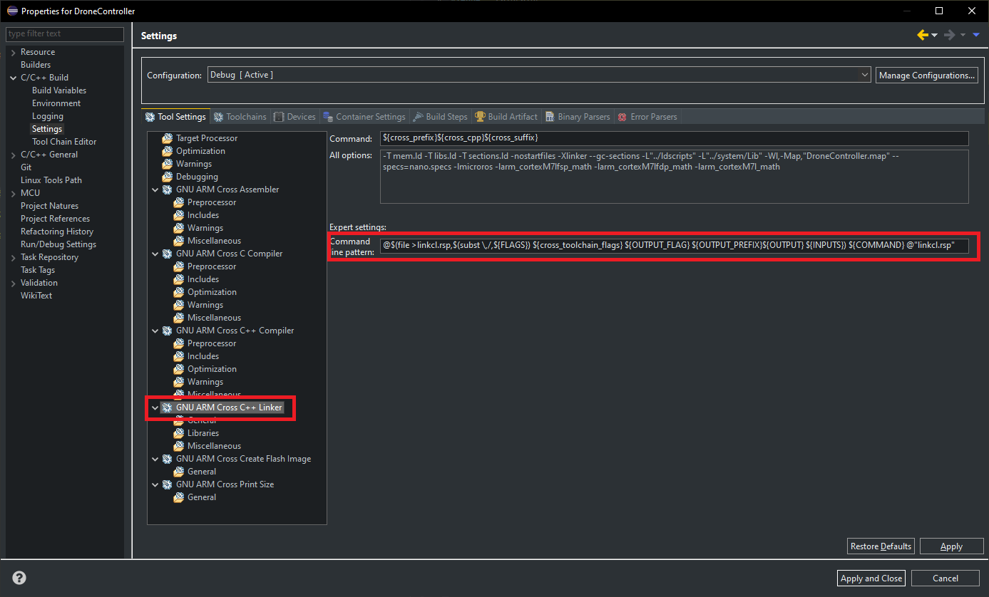
A build error I encountered when building the MCU project after including the Micro-ROS library was GCC Compiler Error, “make (e=87): Error”. This error is caused when the linker command arguments are to long, when the project being built includes a lot of files. This is due to a limitation of the Windows command line which doesn’t allow more then 32000 characters. A simple solution to this is to change the linker command to (source):
@$(file >linkcl.rsp,$(subst \,/,${FLAGS}) ${cross_toolchain_flags} ${OUTPUT_FLAG} ${OUTPUT_PREFIX}${OUTPUT} ${INPUTS}) ${COMMAND} @"linkcl.rsp"In Eclipse this can be found under “Project Settings->C/C++ Build->Settings->Tool Settings->GNU ARM Cross C++ Linker->Expert settings->Command line pattern”, and should look something like this:
Step 4.5 (Optional):
In addition to the required transport and time functions, it is possible to set custom dynamic memory allocation functions, functions that implement “malloc()”, “free()”, “realloc()” and “calloc()” functionality. This is specially useful when a RTOS is used, where it is often desirable to have thread safe, and inside a defined memory region, dynamic memory allocations. A set of allocation functions, that use RT-Thread dynamic memory allocation functions, is shown below:
//Custom allocation function, equivalent of malloc()
static void * rtt_allocate(size_t size, void * state) {
	return rt_malloc(size);
};

//Custom de-allocation function, equivalent of free()
static void rtt_deallocate(void * pointer, void * state) {
	return rt_free(pointer);
};

//Custom re-allocation function, equivalent of realloc()
static void * rtt_reallocate(void * pointer, size_t size, void * state) {
	return rt_realloc(pointer, size);
};

//Custom zero-allocation function, equivalent of calloc()
static void * rtt_zero_allocate(size_t number_of_elements, size_t size_of_element, void * state) {
	return rt_calloc(number_of_elements, size_of_element);
};
With the custom allocation functions created we now have to pass them to the Micro-ROS library. This is done with the “rcutils_set_default_allocator” function, just as shown below:
rcl_allocator_t allocator = rcutils_get_zero_initialized_allocator();
allocator.allocate = rtt_allocate;
allocator.deallocate = rtt_deallocate;
allocator.reallocate = rtt_reallocate;
allocator.zero_allocate = rtt_zero_allocate;
(void)!rcutils_set_default_allocator(&allocator);This section will give instructions on getting Micro-ROS actually running, after the static library has been built and added to the MCU project. This consists of two parts: the Client, running on the MCU, and the Agent, running on the host PC. You will find the basic code that is required for the client as well as how to create and run the agent. How to create a simple subscriber and publisher on the client will also be shown with code examples.
Basic Micro-ROS client (MCU)
Starting on the client side, the minimum steps (and code) required to create and run a Micro-ROS client are listed below. These instructions are based on the Micro-ROS documentation for creating a node.
- Set Micro-ROS custom transport: Using the custom transport functions created in the previous section and set with the function “rmw_uros_set_custom_transport()”.
- Set Micro-ROS custom allocator (Optional): Similarly to setting the custom transport layer, the custom allocation functions must also be first set, if desired. This is done with the function “rcutils_set_default_allocator()”.
- Get Micro-ROS allocator: After the custom allocator has been set, we now need a “link” to it through a structure that holds all allocation functions. This structure must be “global” so that it remains in memory, and so that it can be passed to other Micro-ROS functions. To initialize of the allocator structure, the following function is called “rcl_get_default_allocator()”.
- Initialize Micro-ROS support struct: The next step is to create and initializes the Micro-ROS support structure. This structure again must be a “global” variable so that it remains in memory, and so that it can be passed to other Micro-ROS functions. The initialization of the support structure is accomplished with the function “rclc_support_init()”. This also establishes a connection to the Micro-ROS agent.
- Initialize and create Node: Next we have to create and initialize a Micro-ROS node. The node is saved into a structure, that also must be “global” so that it remains in memory, and so that it can be passed to Micro-ROS functions. The node is created with the function “rclc_node_init_default()”. Besides a pointer to the node structure variable, this functions also takes the name and, optionally, the namespace as arguments. This Micro-ROS node is equivalent to a ROS 2 node, including the significance of the node name and namespace.
- Initialize and create Executor: The final step is creating and initializing the Micro-ROS executor. The executor is responsible for handling Micro-ROS events, like new subscriber messages. The executor is saved into a structure, that again must be “global” so that it remains in memory, and so that it can be passed to some Micro-ROS functions. The executor is created, and initialized, with the function “rclc_executor_init()”. The executor has to be run periodically, with a call of the “rclc_executor_spin_some()” function, for example in the main loop, a RTOS thread or in a timer callback.
Below is the code implementing all the previous steps, creating and starting a Micro-ROS client:
//Required global variables
rcl_allocator_t allocator;
rclc_support_t support;
rcl_node_t node;
rclc_executor_t executor;

rmw_ret_t error;

//Set Communication functions
rmw_uros_set_custom_transport(
	true,
	NULL,
	rtt_transport_open,
	rtt_transport_close,
	rtt_transport_write,
	rtt_transport_read
);

//Set Allocation functions (Optional)
rcl_allocator_t allocator = rcutils_get_zero_initialized_allocator();
allocator.allocate = rtt_allocate;
allocator.deallocate = rtt_deallocate;
allocator.reallocate = rtt_reallocate;
allocator.zero_allocate = rtt_zero_allocate;
(void)!rcutils_set_default_allocator(&allocator);

//Get allocator
allocator = rcl_get_default_allocator();

//Create init_options
error = rclc_support_init(&support, 0, NULL, &allocator);

//Create node
error = rclc_node_init_default(&node, "uROS_Terminal", "", &support);

//Create executor
error = rclc_executor_init(&executor, &support.context, 1, &allocator);

//Call the executor periodically e.g. in the while(1) loop or a thread:
while(1) {
	error = rclc_executor_spin_some(&executor, RCL_MS_TO_NS(100));
}
Testing and running without Micro-ROS Agent
Without running the Micro-ROS agent, running the above code should fail in the “rclc_support_init()” function by returning an error code after about 10s. During this time the following message (or similar) should be sent from the MCU to the PC (over serial) 10 times (defined by “UXR_CONFIG_MAX_SESSION_CONNECTION_ATTEMPTS” in “micro-ROS/uxr/client/config.h”), once per second (defined by “UXR_CONFIG_MIN_SESSION_CONNECTION_INTERVAL” in “micro-ROS/uxr/client/config.h”): “0x7E[~] 0x00[] 0x00[] 0x18[] 0x00[] 0x80[] 0x00[] 0x00[] 0x00[] 0x00[] 0x01[] 0x10[] 0x00[] 0x58[X] 0x52[R] 0x43[C] 0x45[E] 0x01[] 0x00[] 0x01[] 0x0F[] 0x37[7] 0x22[”] 0xE6[] 0x8C[] 0x81[] 0x00[] 0xFC[] 0x01[] 0x05[] 0x75[u]". If these bytes are interpreted as ASCII (in []), it can be seen the “XRCE” text. In case this message is not repeated 10 times, and the function “rclc_support_init()” did not timeout/return an error, there is something wrong in the transport functions and/or the time stamp function “clock_gettime()”.
This error occur to me with the HMI-Board, where the time stamp function “clock_gettime()” did not return the correct timestamp, and therefore the “timeout” value passed to the transport read function read a very high value (way above the normal 1000). This was due to the compiler used in compiling Micro-ROS in linux, and the one for building the HMI-Board firmware in RT-Thread IDE use a different time definition e.g. the standard library “_types.h” had different definitions for “time_t”. Under linux the variable type ("TIME_T") is defined as “__int_least64_t” while in RT-Thread IDE it was defined as “__int_least64_t” (something to due with the packaged compiler with RT-Thread IDE, I did not encounter the same problem with Eclipse). The solution was to copy and past the “time.h” file from the linux compiler (or the one used in Eclipse) to the RT-Thread IDE compiler.
Basic Micro-ROS Agent (PC)
The other part of the basic Micro-ROS setup is the agent, that runs on the host PC. The agent makes the interface between Micro-ROS running on the MCU and ROS 2 running on the host PC, it is the Micro-ROS (and DDS) broker. The agent connects to Micro-ROS running on the MCU over the defined custom interface. For this agent no code has to be written, the agent only has to be built, like any other ROS 2 package and in a similar fashion to how the Micro-ROS static library was built. THe instructions shown here are based on the Micro-ROS documentation for creating a agent.
The instructions assume that the toolchain is already setup, and a Micro-ROS workspace created, just as shown in the Micro-ROS Build and Port section under Step 1: Toolchain setup. It is possible to create a fresh Micro-ROS workspace, or the one created for the Micro-ROS static library build can be reused. With the toolchain setup, we can now call the following bash commands to create and build a Micro-ROS agent:
# Go to the Micro-ROS workspace folder
cd microros_ws

# Source ROS 2
source /opt/ros/humble/setup.bash

# Source local packages
source install/local_setup.bash

# Create Agent
ros2 run micro_ros_setup create_agent_ws.sh

# Build Agent
ros2 run micro_ros_setup build_agent.sh

# Possible ROS Update
sudo rosdep init
rosdep update
After the successful build of the Micro-ROS agent, the following bash commands launch/run the agent:
# Go to the Micro-ROS workspace folder
cd microros_ws

# Source ROS 2
source /opt/ros/humble/setup.bash

# Source local packages
source install/local_setup.bash

# Run Agent (serial connection)
ros2 run micro_ros_agent micro_ros_agent serial --dev /dev/ttyUSB0 -b 921600 -v6
Of these bash commands, the last one is the command that actually launches the Micro-ROS agent. It takes a few arguments, the first being the type of connection to use, here this is a serial connection. This is then followed by two arguments only applicable to a serial connection: “–dev /dev/ttyUSB0” which sets the serial interface to be used (to list all serial interfaces in linux the following bash command can be used: “dmesg | grep tty”), and “-b 921600” which sets the serial interface baudrate (here 921600). The last argument is optional and sets the verbosity, how detailed the terminal output of the agent should be, with options ranging from “-v1” for minimum verbosity to “-v6” for maximum verbosity, with “-v4” being the default.
Testing and running with Micro-ROS Agent
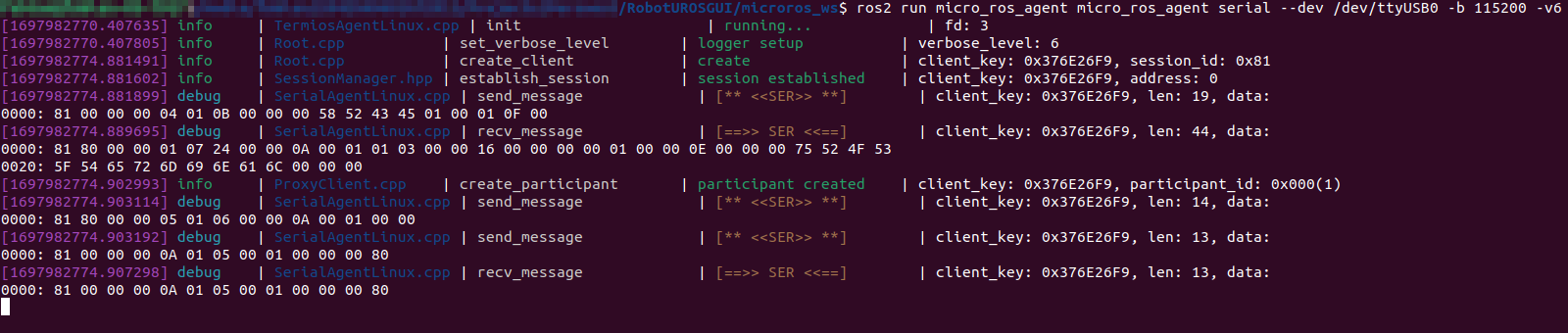
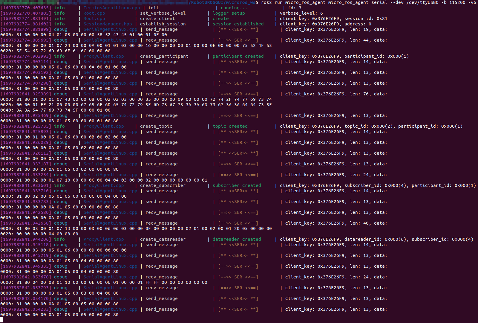
After launching the Micro-ROS agent, the MCU can be connected to the host PC, over a serial interface, and reset to establish a new connection. This then should result in the following Micro-ROS agent terminal output, for verbosity level set to the default aka “-v4” or “-v6”:

Simple Subscriber
With the basic Micro-ROS client and agent setup and running, the next step is to add some actual functionality to our Micro-ROS client. The first example is adding a simple subscriber, subscribing to a ROS 2 topic with the name twist and of type geometry_msgs/Twist. This example is based on instructions found in the Micro-ROS documentation for creating a publisher and subscriber.
To achieve this, we have to create a new subscriber and a callback function that is called every time a new message of the subscribed topic is received. First we create the callback function, with an example on how this function can look shown below:
SubscriberCallbackFunction(const void *msgin) {
	const geometry_msgs__msg__Twist * twistMsg = (const geometry_msgs__msg__Twist *)msgin;
}
With the callback function in place, the subscriber can now be created. Three different types of subscribers can be created, depending on the Quality-of-Service (QoS) desired. The two basic ones are a Reliable (default) and a Best effort subscriber, while the third is to use a custom QoS which is quite a bit more complex and will not be shown in this section. More information on QoS types for Micro-ROS can be found here and for QoS in ROS 2 in general here. In essence, the two types Reliable and Best effort, are self-explanatory. The Reliable QoS makes sure a message is delivered, implying a confirmation for each message and with that detecting errors in the communication and resending if necessary. This makes it more expensive resources wise, not only on RAM and CPU on the MCU but also on communication bandwidth (reduced throughput) and latency. In contrast, the Best effort QoS does not guarantee that a message is delivered, it is send and forget. This makes it less resource expensive and improves both throughput and latency.
Again, as with the node, the subscriber is saved into a structure that must be “global” so that it remains in memory, it is also used/passed for all subscriber related Micro-ROS functions. This structure, and the subscriber itself, is created with the “rclc_subscription_init_default()” or “rclc_subscription_init_best_effort()” functions, depending on if a Reliable or a Best-Effort subscriber should be created. This function also requires the node structure as well as the type of topic message and the name of the topic. The type of topic message can be obtained with the helper function “ROSIDL_GET_MSG_TYPE_SUPPORT()”, with the arguments being the path to the topic type header file (".h") decomposed in it’s part e.g. for the Twist topic the path to the header file is “geometry_msgs/msgs/twist.h” so we use “ROSIDL_GET_MSG_TYPE_SUPPORT(geometry_msgs, msg, Twist)”. The “rclc_subscription_init_xxx()” function also registers the subscriber in the Micro-ROS agent, appearing now as a normal ROS 2 Topic (visible with the “ros2 topic list” command).
After creating and initiating the subscriber, it has to be passed to the executor. This sets the callback function that will be called when a new message of the subscribed topic is received. The subscriber will only work properly if the executor is called periodically, as was mentioned and setup in the basic Micro-ROS client code.
Below is the basic code for creating this Micro-ROS subscriber, to topic type geometry_msgs/Twist and topic name twist, with code for either Reliable or Best-Effort QoS:
//Required global variables
rcl_subscription_t subscriber;
geometry_msgs__msg__Twist twistMsg;

rmw_ret_t error;

//Create new subscriber
error = rclc_subscription_init_default(&subscriber, &node, ROSIDL_GET_MSG_TYPE_SUPPORT(geometry_msgs, msg, Twist), "twist");		//Reliable subscriber
//error = rclc_subscription_init_best_effort(&subscriber, &node, ROSIDL_GET_MSG_TYPE_SUPPORT(geometry_msgs, msg, Twist), "twist");	//Best Effort subscriber

//Add subscriber to executor
error = rclc_executor_add_subscription(&executor, &subscriber, &twistMsg, &SubscriberCallbackFunction, ON_NEW_DATA);
Testing and running with Micro-ROS Agent
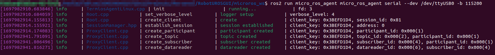
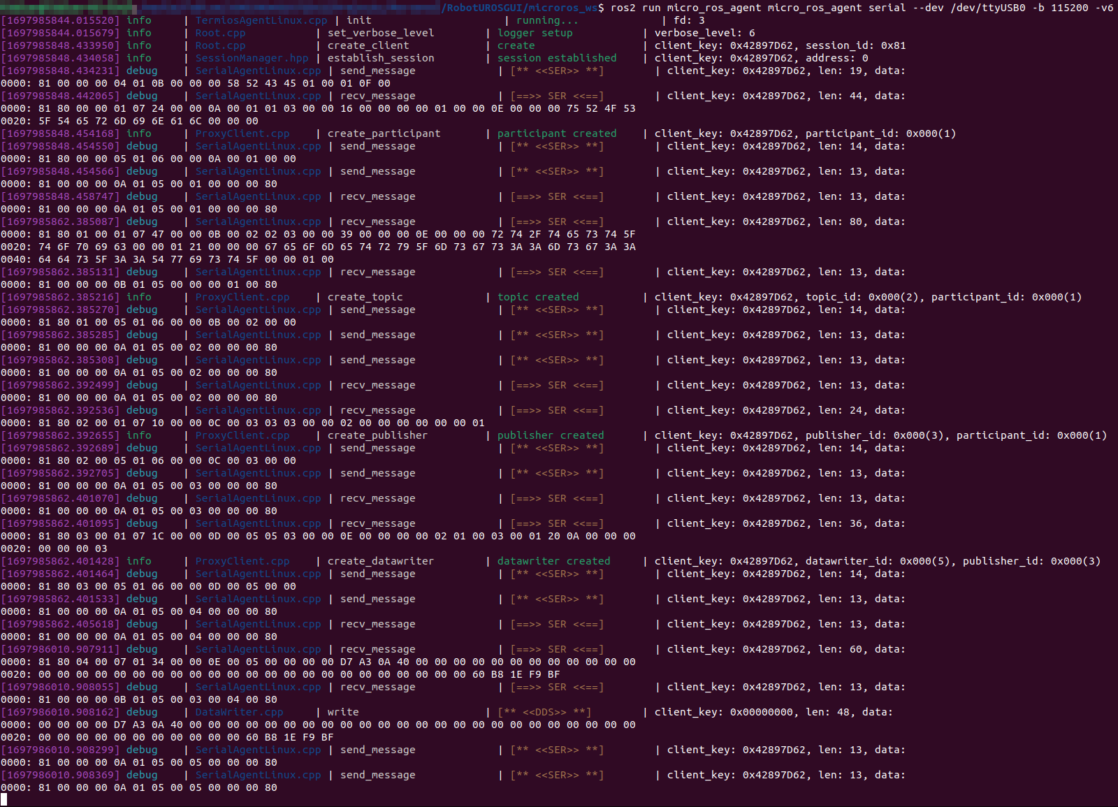
With the subscriber code added, the typical Micro-ROS agent terminal output changes to reflect the newly added subscriber and is shown below, for verbosity level set to the default aka “-v4” or “-v6”:
Simple Publisher
Creating a simple publisher is very similar to how a simple subscriber is created, but even simpler as no callback function or registration to the executor is required. We only have to create the publisher and save it to a structure that must again be “global” so that it remains in memory and will be used/passed for all publisher related Micro-ROS functions. The publisher is created with the “rclc_publisher_init_default()” or “rclc_publisher_init_best_effort()” functions, depending on if a Reliable or a Best-Effort QoS profile for the publisher should be used. This function takes the same arguments as the function for creating a subscriber, so the explanation of the arguments can be see in the Simple Subscriber section, as well as more details on the two different QoS profiles. This example is also based on instructions found in the Micro-ROS documentation for creating a publisher and subscriber.
Below is the basic code for creating this Micro-ROS publisher, to topic type geometry_msgs/Twist and topic name twist, with code for either Reliable or Best-Effort QoS:
//Required global variables
rcl_publisher_t publisher;

rmw_ret_t error;

//Create publisher
error = rclc_publisher_init_default(&publisher, &node, ROSIDL_GET_MSG_TYPE_SUPPORT(geometry_msgs, msg, Twist), "twist");		//Reliable publisher
//error = rclc_publisher_init_best_effort(&publisher, &node, ROSIDL_GET_MSG_TYPE_SUPPORT(geometry_msgs, msg, Twist), "twist");	//Best Effort publisher
This created a new publisher, and registered it with the Micro-ROS agent, appearing now as a normal ROS 2 Topic (visible with the “ros2 topic list” command). To actually send/publish a new message on this topic, the function “rcl_publish()” must be called. This functions takes the created publisher structure as well as the message structure, here a “geometry_msgs__msg__Twist” structure, to be sent as arguments. This function can be called periodically to send/publish the topic periodically. Below is the basic code to publish:
geometry_msgs__msg__Twist twistMsg;
twistMsg.linear.x = 3.33f;
twistMsg.linear.y = 0.00f;
twistMsg.linear.z = 0.00f;
twistMsg.angular.x = 0.00f;
twistMsg.angular.y = 0.00f;
twistMsg.angular.z = -1.57f;
rmw_ret_t error = rcl_publish(&publisher, &twistMsg, NULL);
Testing and running with Micro-ROS Agent
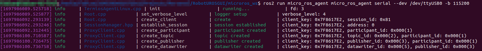
With the publisher code added, and without the subscriber code, the typical Micro-ROS agent terminal output changes to reflect the newly added publisher and is shown below, for verbosity level set to the default aka “-v4” or “-v6” (topic published once):
TBD