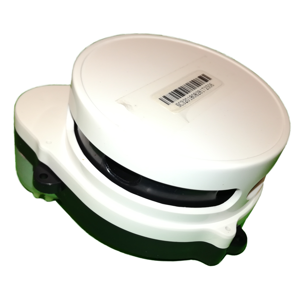
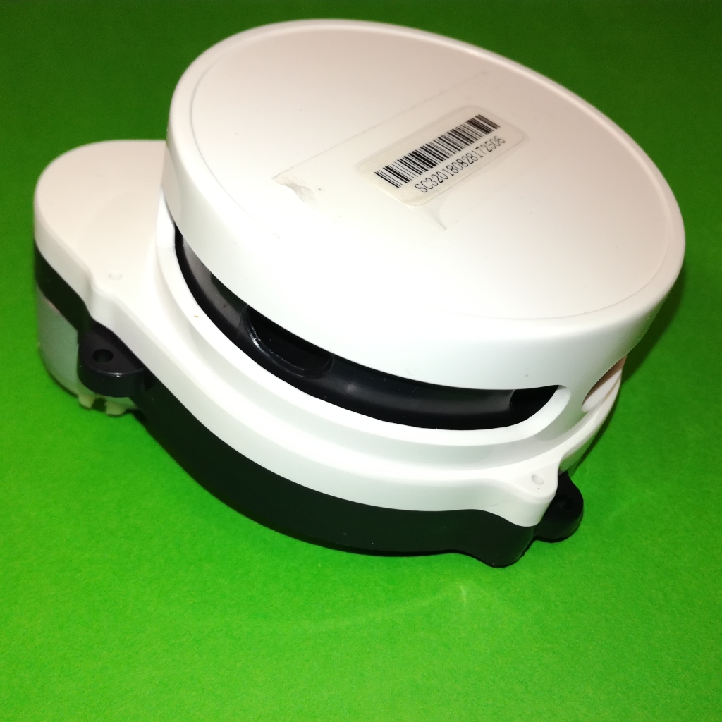
This “project” is the results of a AliExpress expedition afternoon, where I came across a seller that sells recovered parts from consumer electronics, like LiDARs from robot vacuum cleaners, for cheap but without much information or guarantee that they work. I ended up buying one of the LiDARs from the shop for about 20€ incl. shipping, which is quite a bit cheaper then even the cheapest new LiDARs (>60€). Even if it would have turned out to not work it is interesting enough to get, to disassemble and see how it works and maybe even for some parts.
The seller sells different LiDARs but all seem to be based on the same core, the one I ended up buying is the Delta-2G. From the sellers page, and looking around the web, there seem to be a large amount of very similar LiDARs, probably all based and cloned from the same design. These include LiDARs used in Xiaomi robot vacuums (Xiaomi LDS e.g. LDS02RR), the robotics oriented SLAMTEC RPLIDAR A1 or the YDLIDAR X4. I’m not certain who created the original/first design but from the amount of documentation and general information available it seems to be SLAMTEC with the RPLIDAR A1.
As mentioned above, the seller sells the LiDARs without much information so some reverse engineering was necessary, not only to see how these types of LiDARs work and are built but also to see how to use and interface with it. This page is the documentation of this process, where all the information gathered is shared publicly.
Power and Data Transfer
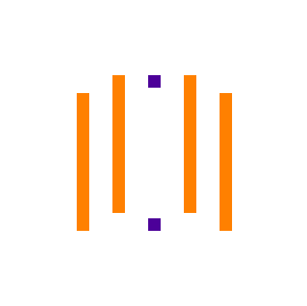
The LiDAR is made up of two parts: a base that doesn’t rotate and is used to mount the LiDAR to a robot or other surface and also has the interface connector, and the head that rotates freely 360º with all the sensors and processing. The way the base communicates and powers the head is clever, it is all wireless with no slip ring or other similar physical interface between them, greatly improving the longevity of the LiDAR. Power is transferred through magnetically coupled coils, similar to wireless charging, that are mounted vertically like tubes. The middle of the tube assembly is hollow, giving a clear optical path from the base PCB to the head PCB. This is used for the data communication between the boards, using a IR emitter on the head and IR receiver on the base.
The simplified overview of this structure can be seen in the block diagram below:
A downside of this approach is power loss from the relatively low efficiency of wireless power transmission. How significant this is still has to be evaluated.
Laser Triangulation
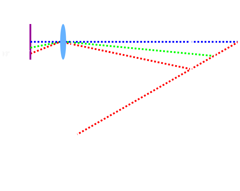
The LiDAR uses laser triangulation to determine the distance to a surface, not time-of-flight (ToF). This is a cheaper and simple way to determine distances using a laser. In this technique, a laser and a optical sensor are mounted horizontally with a small angle between them. The laser therefore emits at a slight angle which means that when it is reflected back it doesn’t return at a straight line but is deviated slightly. How far the laser reflection is deviated away from the laser emitter depends on the distance to the surface, resulting in a simple relationship between this deviation and the distance to the surface. To determine how much the laser point was deviated, and therefore the distance to the surface, a linear image sensor is used together with a lense that collects and focuses the reflected point onto the image sensor.
The simplified diagram of this technique is shown in the block diagram below:
Bottom Side
The first step is to turn the LiDAR module over, and looking at the bottom side. The bottom side holds one PCB which has the connector to interface with the LiDAR module, a 5-pin JST-XH connector, and the name of this specific LiDAR module, Delta2G. Removing the 3 screws holding the PCB down, it can be partially lifted to one side, but carefully as two wires that connect to the power transmission coil are soldered to the PCB and are quite short and fragile. Besides those two wires, the IR phototransistor can be seen facing up through the middle/core of the rotation mechanism, which is used to receive data from the top rotating module.
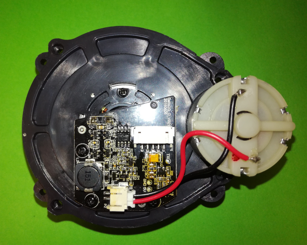
The bottom PCB has the circuitry to generate the AC power signal needed to drive the power transmission coil, used to transmits power to the top rotating module wirelessly. It also has the circuitry necessary to read and boost the IR phototransistor signal to a clean digital signal (UART).
Using the AliExpress sellers images, after passing them thorough a image translator, and by probing the bottom PCB test points and motor, the following pinout for the interface connector is obtained:
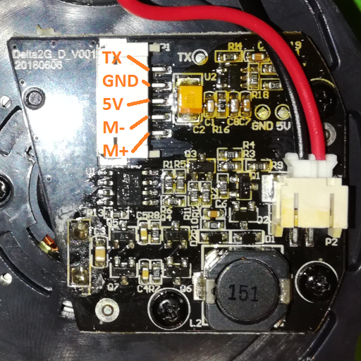
From this it can be see that this specific LiDAR module does not have a RX line, so it can not receive any commands and therefore no configurations can be changed, at least through this interface connector. Also, the motor is connected directly to the interface connector, so motor control must be done externally either through the voltage supplied to it, or with a H-Bridge and a PWM control signal.
Top Uncovered
Next lets take a look at the main part of the LiDAR module, the top/head rotating part. To get access to this, two covers have to be removed, first the outer white cover and then a smaller black cover that only covers the rotating part. With both removed, the heart of the LiDAR module can be seen: laser emitter on the left, optical sensor on the right and the control and processing PCB on the back.
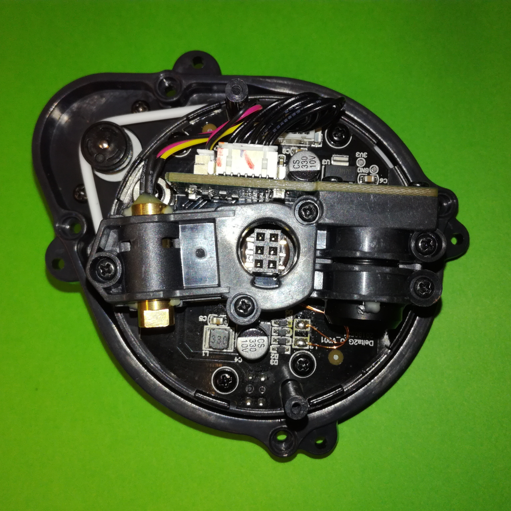
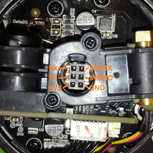
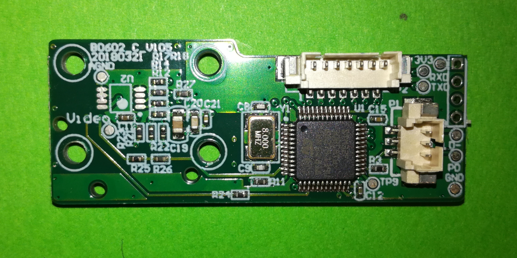
All the processing is performed on the back side PCB, on a STM32F302C8T6 MCU, while the bottom PCB has the power management (AC rectification, smoothing and LDO) and IR LED driver on it. Looking top down at the head, another connector can be seen at the center, a 6-pin standard 2.54mm header. By probing the control PCB test points, the pinout of this connector was obtained and from this it is obvious that it is the debugging and programming connector. It gives access to the debug interface pins of the MCU (pin 37 aka PA14/SWCLK and pin 34 aka PA13/SWDIO) as well as to both the TX and RX lines of the control interface UART:
Sensor Board
To get a better idea on how the LiDAR module works, the main PCB is removed. On the backside of it is the MCU, the clock source, the connector to the bottom PCB and to the laser diode module, and some analog signal conditioning for the optical sensor.
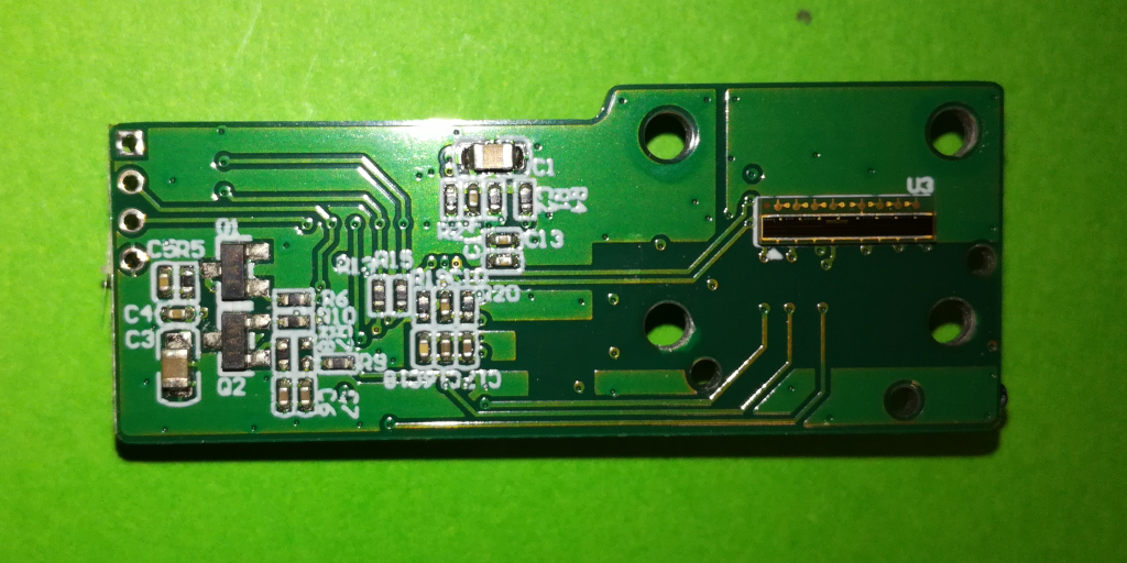
The interesting part is on the other side, where on the left side the control circuit of the laser diode is located, two transistors and some resistors, and on the right side the optical sensor, a linear image sensor:
The linear image sensor is a BGA part with 8 contacts at the bottom and looking with a magnifying glass at the sensor silicon, the markings LI163-7 can be seen:
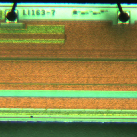
Now this doesn’t help much to figuring out what linear image sensor it is, but by searching AliExpress and eBay for linear image sensors we can find one that looks exactly like the one on the PCB, the S13131-1536 from Hamamatsu. Checking the datasheet for this sensor it is very likely that this is the one used. It is therefore a CMOS sensor with 1536 pixels and integrated timing generator, with an analog video output at a maximum frequency of 2 MHz, and a minimum full frame time of 776 us, aka a maximum “frame rate” of 1288 fps.
As there is no information about the communication interface, not even if the interface is a UART interface (from the single TX line this is assumed), first it was necessary to discover the basic characteristics of the TX signal. To get these, and specially to discover the datarate (baud rate), the TX pin is connected to an oscilloscope. In idle, the head not rotating, no signal appears on the TX line. Only when slowly rotating the head by hand a signal appears and from which the datarate was obtained. It is 115200 so a typical UART baud rate. A FTDI is then connected to the TX line and the standard UART settings, 8-N-1, were used and worked perfectly:
- Baud rate: 115200bps
- Data Size: 8-Bits
- Parity: None
- Stop bits: 1 bit
- Flow Control: None
During this test, rotating the head slowly by hand, the following data is output over the UART interface:
AA 00 09 01 61 AE 00 01 0C 01 D0
AA 00 09 01 61 AE 00 01 0D 01 D1
AA 00 09 01 61 AE 00 01 0C 01 D0
This is clearly a to short message to include any range information. Connecting the motor and using it to rotate the head it was possible to observe that messages in the style above are output when the rotation speed (RPM) is to low or to high, only in a specific range the output data switches to much longer messages, like the ones shown below:
AA 00 61 01 61 AD 00 59 5B 00 12 00 00 86 3C 9E 9B 02 4B 3C 39 B9 (...) A0 04 B8 A1 04 B7 25 E7
AA 00 61 01 61 AD 00 59 5A 00 12 09 60 A0 04 BC 99 25 F9 99 26 12 (...) A1 05 3A 9F 05 3D 1D 64
AA 00 61 01 61 AD 00 59 5B 00 12 12 C0 A0 05 44 A1 05 4E A0 05 53 (...) 7E 06 B2 98 06 C6 23 90
AA 00 61 01 61 AD 00 59 5B 00 12 1C 20 9A 06 D4 99 07 87 9B 07 1D (...) 3D 0A BA A0 0B 63 21 EF
AA 00 61 01 61 AD 00 59 5A 00 12 25 80 A2 0B 49 A2 0B 17 A3 0B 02 (...) A0 09 EB 66 09 A8 22 BE
AA 00 61 01 61 AD 00 59 5C 00 12 2E E0 A1 09 D7 A1 09 D1 A0 09 D0 (...) 00 00 00 00 00 00 24 D9
AA 00 61 01 61 AD 00 59 5B 00 12 38 40 00 00 00 38 04 93 38 04 9B (...) 00 00 00 00 00 00 04 FE
AA 00 61 01 61 AD 00 59 5A 00 12 41 A0 00 00 00 00 00 00 00 00 00 (...) 00 00 00 00 00 00 04 56
AA 00 61 01 61 AD 00 59 5A 00 12 4B 00 00 00 00 00 00 00 00 00 00 (...) 9D 01 FC 9C 02 01 06 F6
AA 00 61 01 61 AD 00 59 59 00 12 54 60 81 02 10 9A 02 37 9C 02 3F (...) A3 02 41 A3 02 44 1A BB
AA 00 61 01 61 AD 00 59 5A 00 12 5D C0 A1 02 45 9D 02 40 9D 02 3E (...) 9C 02 4C 9B 02 4E 1C 23
AA 00 61 01 61 AD 00 59 5A 00 12 67 20 9C 02 52 9A 02 57 9B 02 5A (...) 8E 02 D0 9A 02 D9 23 54
AA 00 61 01 61 AD 00 59 5A 00 12 70 80 9F 02 DF A0 02 EC A1 02 F1 (...) 00 00 00 00 00 00 16 A9
AA 00 61 01 61 AD 00 59 5B 00 12 79 E0 00 00 00 00 00 00 00 00 00 (...) 94 44 E0 98 41 28 17 67
AA 00 61 01 61 AD 00 59 5A 00 12 83 40 97 3E EF 6D 3C CF 8E 3A E5 (...) 71 2E E0 00 00 00 12 0E
Analyzing both types of messages, it is possible to guess part of the message structure, appearing to be something like this:
| Byte # | 0 | 1 | 2 | 3 | 4 | 5 | 6 | 7 | 8 -> N-3 | N-2 | N-1 |
|---|---|---|---|---|---|---|---|---|---|---|---|
| Meaning: | Sync 0 | Sync 1 | Length | N/A | N/A | N/A | N/A | Payload Length | Payload | CRC | CRC |
In case of the short message, output at the incorrect RPM range, the payload is very short and seems to be only the RPM value:
| Byte # | 7 | 8 | N-2 | N-1 |
|---|---|---|---|---|
| Meaning: | 0x01 | RPM | CRC | CRC |
For the long, range data, message, the payload is much larger with the initial bytes appearing to be information about the current message: the RPM value (apply x3 scaling ?) and the start (?) angle of the measurements in x100 degrees and MSB first. This is then followed by a large amount of bytes that seem to be in groups of 3 (when 0x00 appears they come in multiples of 3), which must be the ranging sample data. From looking more at those 3 byte groups and converting them to integers, it is clear that the first byte is the signal quality and the two following bytes are the actual range data in 0.25mm and MSB first. The long messages have therefore a structure as follows:
| Byte # | 7 | 8 | 9 | 10 | 11 & 12 | 13 -> 15 | 16 -> 18 | (…) | N-5 -> N-3 |
|---|---|---|---|---|---|---|---|---|---|
| Meaning: | Payload Length | RPM | N/A | N/A | Start Angle | Sample #1 | Sample #2 | (…) | Sample #M |
It is also possible to observe that the number of samples (M) in the current message can be calculated from the payload length by subtracting the other payload bytes (5) and dividing by the number of bytes per sample (3):
$$ M = {{ Payload Length - 5 } \over 3} $$
Other LiDAR Protocols
A fellow hobbyist, after coming across this page about the Delta-2G LiDAR, informed me that there is another chinese LiDAR which seems to use the same or very similar interface protocol, and that all the relevant information for that LiDAR is available: datasheet, protocol description and SDKs. The LiDAR in question is one from 3irobotix, from their Delta series of LiDARs (Delta-1A, Delta-2A, Delta-2D, Delta-3A). All the files for this series of LiDARs can be downloaded from here, a link from a AliExpress listing of one of those LiDARs.
By analyzing the interface protocol for each of them, after passing the relevant pdf through a translator, it is clear that they all use basically the same protocol, and that is also matches with my observed protocol used by the Delta-2G. This allowed me to complete and correct the basic message structure for the Delta-2G LiDAR as well. The basic message structure is as follows:
| Byte # | 0 | 1 & 2 | 3 | 4 | 5 | 6 & 7 | 8 -> N-3 | N-2 | N-1 |
|---|---|---|---|---|---|---|---|---|---|
| Meaning: | Header | Length | Protocol | Type | Command | Payload Length | Payload | CRC | CRC |
With the main changes between the different LiDARs being the value for each field, and the CRC algorithm used. For the Delta-2G case the following values, and CRC, are used:
- Frame Header: 0xAA
- Protocol Version: 0x01
- Frame Type: 0x61
- CRC: 16-Bit cumulative sum
From the documents we can also gather that data is transmitted in the payload field, with the command field identifying what the payload contains. There are only two different payloads, each with their own command field value:
- 0xAE: “Device Health”, only the RPS/RPM value
- 0xAD: “Measurement Information”, a LiDAR scan message
This two message types match with my observations as well and from the datasheet I also got confirmation for their respective payload structure and value conversion/scaling:
The “Device Health” (0xAE) payload it is exactly as I observed, 1 single byte holding a scaled value for the RPM/RPS with a scaling factor of x0.05 to RPS, or x3 to RPM.
The “Measurement Information” (0xAD) payload also matches with my observation, adding clarification to some bytes I was unsure of as well as confirming value scaling. The payload structure is as follows:
| Byte # | 0 | 1 & 2 | 3 & 4 | (5 + 3N) | (5 + 3N) + 1 | (5 + 3N) + 2 |
|---|---|---|---|---|---|---|
| Meaning: | RPM | Offset Angle | Start Angle | Signal Quality #N | Distance MSB #N | Distance LSB #N |
With the scaling for the angle information being x0.01 degrees and for the distance information x0.25 mm. The offset angle value can be ignored, I don’t understand yet well its significance. Also, the number of samples (M) in each of these messages can be obtained with the following formula:
$$ M = {{ Payload Length - 5 } \over 3} $$
For the Delta-2G each complete rotation is composed of 15 messages (all other LiDARs according to there datasheet use 16 messages) and therefore each “Measurement Information” (0xAD) message contains the information for only a 360/15 = 24 degree slice of the scan. Using this, the corresponding angle for each sample can also be calculated, with N the sample index in the current message:
$$ Angle = Start Angle + {24 \over M} N $$
Finally, the CRC field for the Delta-2G LiDAR is simply a cumulative 16-Bit sum of all bytes from the Header (including) to the CRC (excluded).
Software
Based on the reverse engineered interface protocol above, I wrote some simple scripts (C# and Python) to read and decode the UART messages. Also, I implemented a ROS2 publisher based on the python version of the script, which publishes a fully populated sensors_msgs/LaserScan message whenever a full, 360 degrees, scan is received and decoded. A ROS1 version may follow as well.
The scripts are available in the MiniCubeRobot-Hub GitHub page, or they can be downloaded from below:
Script (C#): LiDARConnection.cs
Script (Python): LiDARConnection.py
This section is dedicated to showing test and characterization results of the LiDAR module.
Power Consumption
The power consumption of the module was measured at the 5V power input at the interface connector, both at idle and during ranging:
Idle: 0.35A @ 5V Ranging: 0.37A @ 5V
From this it can be seen that the LiDAR module has a significant power consumption, over 1.75 Watts, and that ranging does not effect the consumption much. How much of the power consumption is lost in the wireless power transfer has to be evaluated still, but it is probably significant. In ranging mode, there is also the consumption of the motor that must be taken into account, which has a very similar current consumption over the full voltage range (0V to 5V) at just below 0.1 A.
RPM vs Resolution
To get an idea of the relationship between motor drive voltage and LiDAR head RPM, as well as the resulting angular resolution, a test was performed with the results shown in the figure below:
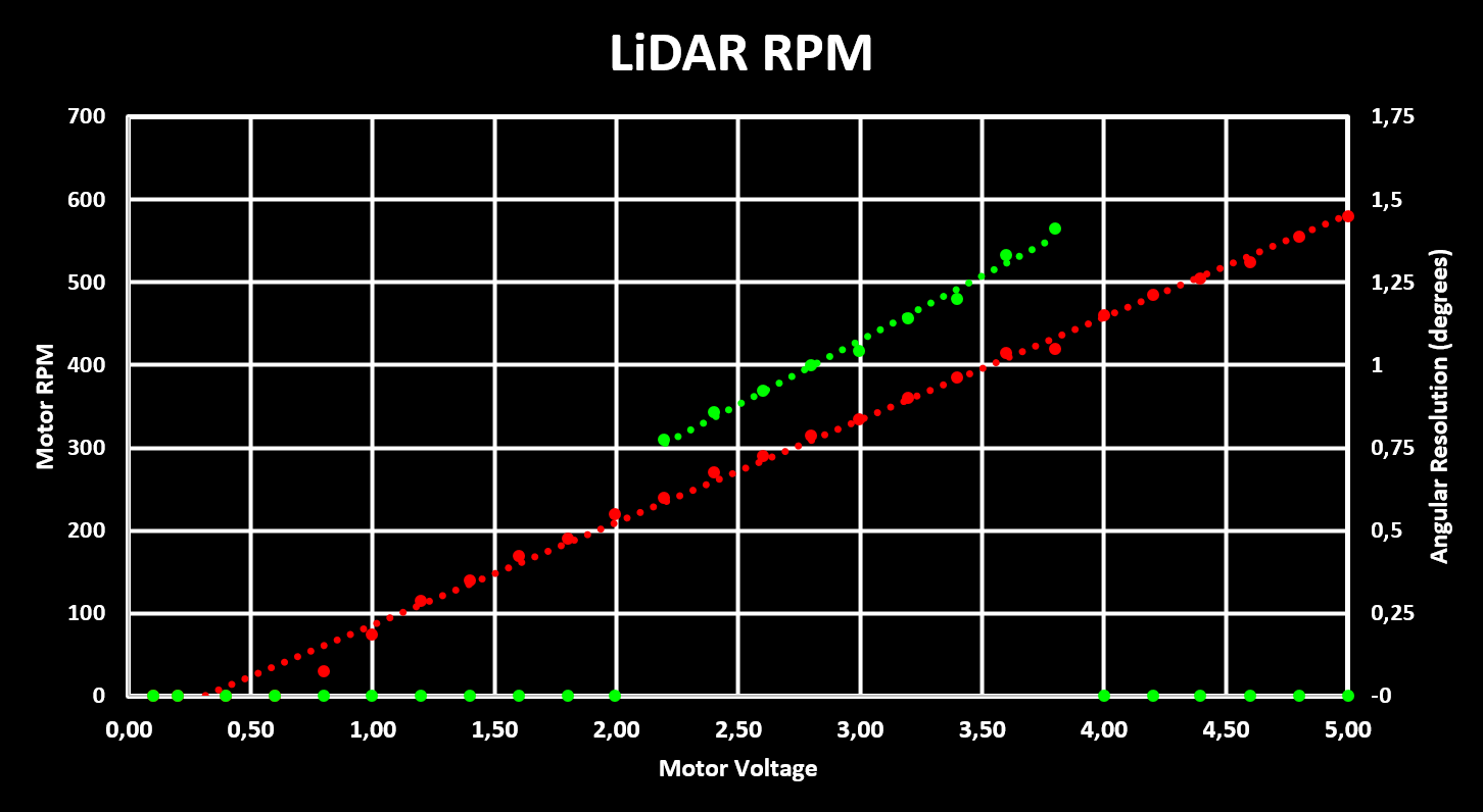
It can be seen that the ranging works in the RPM range from ~240 to ~420 RPM, and that the overall sampling rate is kept constant at close to 2000 sps. This means that the angular resolution is lower the higher the RPM, decreasing from 0.77 degrees to 1.41 degrees over the working RPM range. This angular resolution is in reality the angular distance between two points, if the LiDAR can actually resolve with that angular resolution is to be determined.
The raw data gathered is shown in the table below:
| Motor Voltage | RPM | Ranging | Ranging Points | Angular Resolution | Sampling Rate | Scan Refresh Rate |
|---|---|---|---|---|---|---|
| 0.1 V | 0 | NO | 0 | 0.00 deg | 0 sps | 0 Hz |
| (…) | 0 | NO | 0 | 0.00 deg | 0 sps | 0 Hz |
| 0.8 V | 30 | NO | 0 | 0.00 deg | 0 sps | 0 Hz |
| (…) | (…) | NO | 0 | 0.00 deg | 0 sps | 0 Hz |
| 2.2 V | 240 | YES | 465 | 0.77 deg | 1860 sps | 4.00 Hz |
| 2.4 V | 270 | YES | 420 | 0.86 deg | 1890 sps | 4.50 Hz |
| 2.6 V | 290 | YES | 390 | 0.92 deg | 1885 sps | 4.83 Hz |
| 2.8 V | 315 | YES | 360 | 1.00 deg | 1890 sps | 5.25 Hz |
| 3.0 V | 335 | YES | 345 | 1.04 deg | 1925 sps | 5.83 Hz |
| 3.2 V | 360 | YES | 315 | 1.14 deg | 1890 sps | 6.00 Hz |
| 3.4 V | 385 | YES | 300 | 1.20 deg | 1925 sps | 6.42 Hz |
| 3.6 V | 415 | YES | 270 | 1.33 deg | 1865 sps | 6.92 Hz |
| 3.8 V | 420 | YES | 255 | 1.41 deg | 1785 sps | 7.00 Hz |
| 4.0 V | 460 | NO | 0 | 0.00 deg | 0 sps | 0 Hz |
| (…) | (…) | NO | 0 | 0.00 deg | 0 sps | 0 Hz |
| 5.0 V | 580 | NO | 0 | 0.00 deg | 0 sps | 0 Hz |
Ranging Scan
Using the reverse engineered interface protocol and the developed simple C# script as well as the MiniCubeRobot Hub Unity project, a full LiDAR ranging scan is obtained and rendered and shown in the figure below, where each point in the point cloud has a different color based on its range index (its angular position).
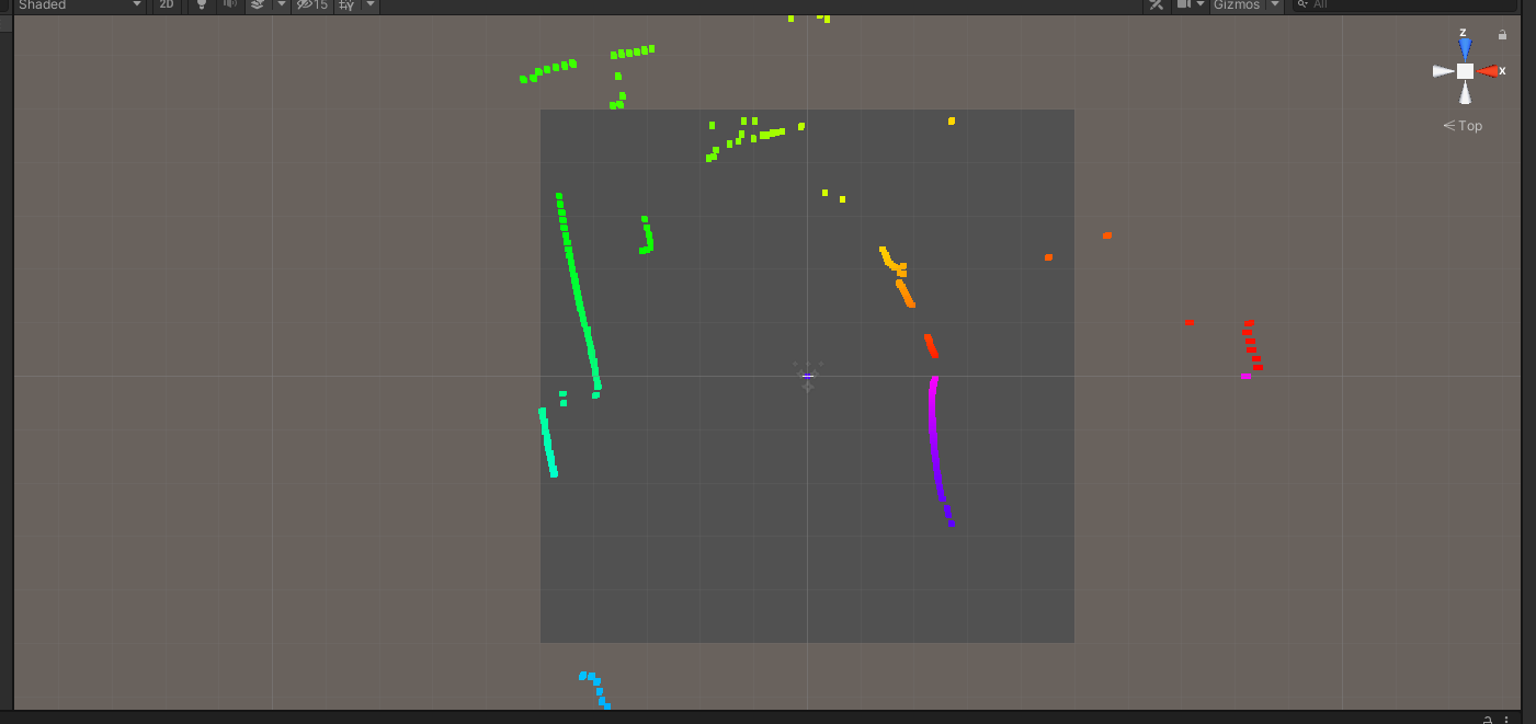
This validates both the reverse engineered interface protocol as well as the C# script used to receive and decode the UART packages.