
Digital Signal Processing (DSP) is a fundamental for efficiently analyzing and manipulating signals in various applications, from audio processing to communications. As DSP tasks increasingly move to the edge and are integrated into MCUs, modern microcontrollers are not only incorporating DSP-specific instructions but also more specialized DSP accelerators. Examples include FMAC (Fused Multiply-Accumulate), CORDIC (COordinate Rotation DIgital Computer), and ADC oversampling found in STM32G4 and STM32H7 series. These accelerators are designed to optimize specific mathematical operations and data conversion processes, providing significant improvements in speed. By offloading some of these repetitive DSP tasks from the MCU core, they enable us to achieve better performance in real-time signal processing applications.
One of the most versatile and powerful accelerators implemented in some MCUs is a CORDIC (COordinate Rotation DIgital Computer). CORDIC is a successive approximation algorithm designed for efficiently computing trigonometric, hyperbolic, and logarithmic functions, using iterative rotations and shifts, only requiring 3 basic operations: additions/ subtractions, bitshifts and lookup tables. There multiplier-less nature makes them ideal for hardware implementation (e.g. in silicon as coprocessors or in FPGA). To keep them simple, their main advantage, CORDICs generally operate with fixed-point numbers rather than floating-point. This combination makes CORDIC a very powerful accelerator in signal processing and control, and other applications, where those functions are commonly used.
In the STM32 MCUs, such as the STM32G4 and STM32H7, the CORDIC is implemented as a coprocessor that can run parallel to the MCU core enabling not only faster calculations but also in parallel with other CPU tasks. This hardware CORDIC offers a maximum precision of 24-bits. It can compute functions like sine, cosine, phase and modulus (atan2), arctangent, hyperbolic functions, natural logarithms and square roots. The precision is determined by the number of iterations are performed, with 24-bits precision reached after about 24 iterations (1 bit per iteration). The number of iterations is programable, by defining the number of cycles of the CORDIC engine where one cycle corresponds to 4 iterations. Because operations are performed using fixed-point numbers, the input and output values to the CORDIC have to be scaled appropriately. For trigonometric functions, angles are scaled to the range of $-\pi$ to $\pi$, and arguments in the atan2 are expected to be in the range of $-1$ to $1$.
Admitting that the CORDIC will be used with 16-bit numbers, the angle can be converted to and from the CORDIC format by multiplying by $\pi/2^15$ (in radians). Bellow is example code to initialize the CORDIC for cosine/sine, arctangent or atan2 functionality. Full precision for 16-bit numbers is reached, for all cases, after 16 iterations (4 cycles).
//Peripheral clock enable
LL_AHB1_GRP1_EnableClock(LL_AHB1_GRP1_PERIPH_CORDIC);

//Configure CORDIC peripheral: Sine and Cosine
LL_CORDIC_Config(CORDIC,	LL_CORDIC_FUNCTION_COSINE,		//Cosine function
							LL_CORDIC_PRECISION_4CYCLES,	//Max precision for Q1.15
							LL_CORDIC_SCALE_0,				//No scale
							LL_CORDIC_NBWRITE_1,			//One input data: angle. Second input data (modulus) is 1 after cordic reset
							LL_CORDIC_NBREAD_1,				//Two output data: cosine, then sine
							LL_CORDIC_INSIZE_16BITS,		//Q1.15 format for input data
							LL_CORDIC_OUTSIZE_16BITS);		//Q1.15 format for output data

//Configure CORDIC peripheral: Arctangent (atan)
LL_CORDIC_Config(CORDIC,	LL_CORDIC_FUNCTION_ARCTANGENT,	//ArcTan function
							LL_CORDIC_PRECISION_4CYCLES,	//Max precision for Q1.15
							LL_CORDIC_SCALE_7,				//No scale
							LL_CORDIC_NBWRITE_1,			//One input data: Value of x=tan(angle)
							LL_CORDIC_NBREAD_1,				//One output data: angle
							LL_CORDIC_INSIZE_16BITS,		//Q1.15 format for input data
							LL_CORDIC_OUTSIZE_16BITS);		//Q1.15 format for output data

//Configure CORDIC peripheral: Two-argument Arctangent (atan2)
LL_CORDIC_Config(CORDIC,	LL_CORDIC_FUNCTION_PHASE,		//Phase/ArcTan2 function
							LL_CORDIC_PRECISION_4CYCLES,	//Max precision for Q1.15
							LL_CORDIC_SCALE_0,				//No scale
							LL_CORDIC_NBWRITE_1,			//Two input data: X coordinate and Y coordinate
							LL_CORDIC_NBREAD_1,				//Two output data: angle and modulus
							LL_CORDIC_INSIZE_16BITS,		//Q1.15 format for input data
							LL_CORDIC_OUTSIZE_16BITS);		//Q1.15 format for output data
After initializing the CORDIC for the desired function, the use of it is as simple as to write the arguments to its input register to trigger the start of the CORDIC, and then read the results. Although the CORDIC provides a data-ready flag, it normally is not required to wait for this flag before reading the results. In 16-bit mode, input arguments are written to a single 32-bit register, with the first 16-bit argument packed into the lower bits and the second argument in the higher. Results are also read from a single 32-bit register, with the two CORDIC return values packet into a single 32-bit value, again the lower bits hold the first return value and the higher the second. Contrary to the write operation, where one 32-bit write is sufficient, here two reads must be performed to reset the CORDIC, with the second read being discarded in 16-bit mode.
Bellow is example code for using the CORDIC to calculate the sine and cosine of an angle, with the input angle assumed to be in Q3.13 radians. The CORDIC in this mode outputs both the cosine and sine of the angle, returned as the first and second value respectively.
Code to run the CORDIC, for Sine or Cosine:
//Scale angle to fit Q1.15 format (divide by PI)
angle = ((int32_t)angle * 10430) >> 13;		//1/PI in Q1.15 is 10430

//Write Angle
uint32_t tmp = 0x7FFF0000 | (uint16_t)angle;		//High part is ARG2, low part ARG1
LL_CORDIC_WriteData(CORDIC, tmp);

//Read Sine and Cosine
tmp = LL_CORDIC_ReadData(CORDIC);	//High part is RES2, low part is RES1
LL_CORDIC_ReadData(CORDIC);			//Second dummy read to clear CORDIC engine

*cosine = (int16_t)(tmp & 0xFFFF);
*sine = (int16_t)(tmp >> 16);
Bellow is example code for using the CORDIC to calculate the arctangent of a value, with the input value ($x$) assumed to be in $x2^{-7}$ format e.g. $x$ has to be pre-scaled/divided by $2^7$ (see the “LL_CORDIC_SCALE_7” scale value used in the initialization of the CORDIC for arctangent operation). The CORDIC in this mode outputs only the arctangent of $x$, returned as the first return value and scaled to $[-\pi,\pi]$.
//Write value x=atan(angle)
uint32_t tmp = 0x7FFF0000 | (uint16_t)tan;		//High part is ARG2, low part ARG1
LL_CORDIC_WriteData(CORDIC, tmp);

//Read ATan
tmp = LL_CORDIC_ReadData(CORDIC);	//High part is RES2, low part is RES1
LL_CORDIC_ReadData(CORDIC);			//Second dummy read to clear CORDIC engine

//Scale value to angle data
tmp = (int16_t)(tmp & 0xFFFF);					//Mask only RES1
tmp = (((int32_t)tmp << 7) * 25735) >> 15;		//Scale back to radians, multiply by PI and the scaling factor used

*angle = tmp;
Finally, and maybe the most useful example is using the CORDIC to calculate the two-arguments arctangent, which takes a vector and calculates its angle and modulus. Here the two input arguments are the vector components $x$ and $y$, scaled to $[-1,1]$ in Q1.15 ($[-32767, 32767]$), with $x$ being the first argument and $y$ the second. The output of the CORDIC is then the angle, returned as the first argument and the modulus, returned as the second argument. Also here the angle is scaled to the range $[-\pi,\pi]$.
//Write Angle
uint32_t tmp = (((uint16_t)y) << 16) | (uint16_t)x;		//High part is ARG2, low part ARG1
LL_CORDIC_WriteData(CORDIC, tmp);

//Read Phase/ATan2
tmp = LL_CORDIC_ReadData(CORDIC);	//High part is RES2, low part is RES1
LL_CORDIC_ReadData(CORDIC);			//Second dummy read to clear CORDIC engine

//Scale value to angle and modulus data
*angle = (int16_t)(tmp & 0xFFFF);				//Mask only RES1
*angle = (((int32_t)*angle) * 25735) >> 15;		//Scale back to radians, multiply by PI
*modulus = (int16_t)(tmp >> 16);
Benchmark
To get an idea of the benefits of using the CORDIC, STM themselves state that using it in 16-bit mode and 32-bit modes, the CORDIC is around 5x faster then using the ARM CMSIS-DSP Library for sine and cosine calculations (arm_sin_q15() or arm_sin_q31()). I did not find results for arctangent and atan2. To verify these claims, and see the performance for the other functions, a simple performance test was made. Using an STM32G473 MCU running at 170 MHz, with the CORDIC also running at 170 MHz, a buffer of 1024 samples was processed with both the CORDIC and ARM CMSIS-DSP library (only the Q15 version). Due to the current CMSIS-DSP library version provided by STM not including arctangent (atan or atan2) functions, only the sine values were compared. Also, because the CORDIC always computes both sine and cosine simultaneously, results were compared with ARM CMSIS-DSP calculating sine alone or both sine and cosine.
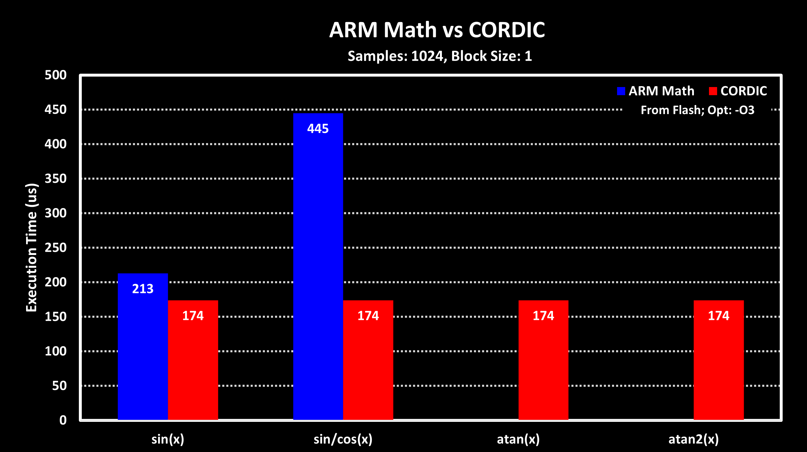
From these results, it can be seen the CORDIC is indeed faster than using ARM CMSIS-DSP Library, although if only sine (or cosine) is required not by a lot. If both are required, then the CORDIC in this test was about 2.5x faster than using CMSIS-DSP functions for Q15 numbers. These results are quite a bit lower than the 5x speedup provided by STM, which may be due to overhead of looping over the 1024 samples in this benchmark (each sine calculation occurs inside the loop). I plan to repeat these tests with a newer CMSIS-DSP version that includes arctangent functions.
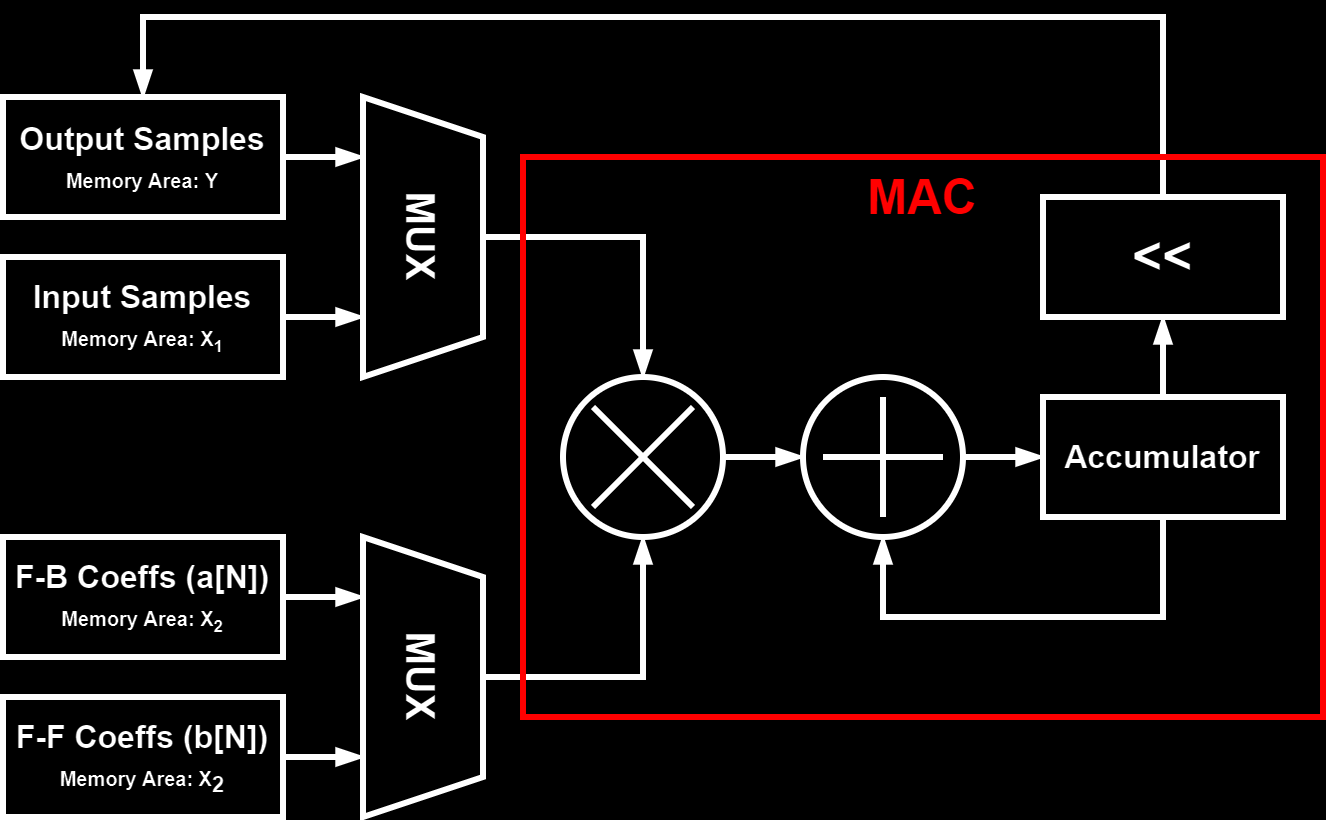
Another powerful DSP accelerator are dedicated hardware modules for filter math, enabling running simple FIR and IIR filters independently and in parallel to the MCU core. An example of such accelerators implemented in modern MCUs is the Filter Math ACCelerator (FMAC) unit in the newer STM32 MCUs, e.g. in the STM32G4 and some STM32H7 series MCUs. The FMAC unit performs multiply and accumulate (MAC) operations over a vector/array of 16-bit fixed point values using its local 256 word (16-bit) memory. This local memory is split into three areas: two for input data ($ X_1 $ and $ X_2 $) and one for output data ($ Y $).
Below is a block diagram of the FMAC unit and how the different memory areas are connected to the MAC. The configuration of the MUX is what defines what type of filter is implemented:
FIR Filter
For FIR filters, the FMAC local memory areas are used as follows: $ X_1 $ for input data, $ X_2 $ for the filter coefficients and $ Y $ for the output data. Because for a FIR filter N previous input data are multiplied and summed together, feed-forward, the input buffer has to be of length equal or greater then the number of filter coefficients. The figure below shows an example on how to organize the local memory:
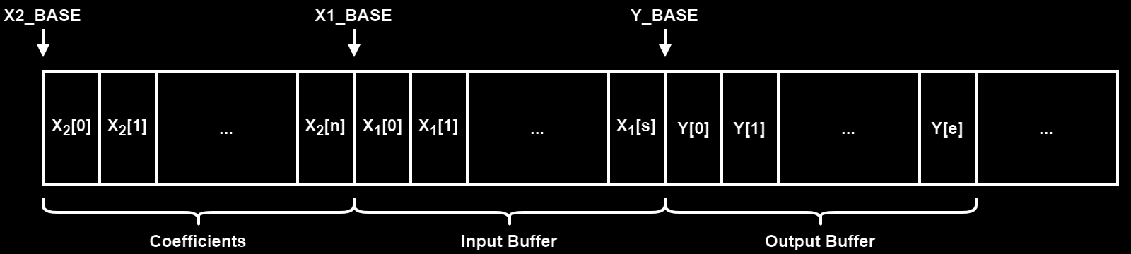
To set-up the local memory like in the figure above, the code below is used:
//Set the coefficient buffer
LL_FMAC_SetX2Base(FMAC, 0);
LL_FMAC_SetX2BufferSize(FMAC, n);

//Set the input buffer
LL_FMAC_SetX1Base(FMAC, n);
LL_FMAC_SetX1BufferSize(FMAC, s);
LL_FMAC_SetX1FullWatermark(FMAC, LL_FMAC_WM_0_THRESHOLD_1);		//X1 area full watermark, when the X1FULL flag is set

//Set the output buffer
LL_FMAC_SetYBase(FMAC, n + s);
LL_FMAC_SetYBufferSize(FMAC, e);
LL_FMAC_SetYEmptyWatermark(FMAC, LL_FMAC_WM_0_THRESHOLD_1);		//Y area empty watermark, when the YEMPTY flag is set
After setting up the local memory areas the coefficient area ($ X_2 $) has to be initialized, filled with the filter coefficients. The input data area can be initialized to so that the filter outputs data faster, the FMAC only starts running when the input area has at least N elements (number of tabs) in it. The code below initializes the coefficients area and also pre-fills the input area with N (number of tabs) zero elements (0x00):
//Load X2 buffer (Coefficient buffer)
LL_FMAC_SetFunction(FMAC, LL_FMAC_FUNC_LOAD_X2);
LL_FMAC_SetParamP(FMAC, n);			//Number of values to be loaded into X2 buffer @ X2_BASE
LL_FMAC_SetParamQ(FMAC, 0);			//Number of values to be loaded into X2 buffer @ X2_BASE + N (only used for IIR filter)
LL_FMAC_SetParamR(FMAC, 0);			//Not used
LL_FMAC_EnableStart(FMAC);			//Start FMAC processing

for(i = 0; i < n; i++) {
	LL_FMAC_WriteData(FMAC, firCoeffQ15[i]);
}

//Load empty values to input buffer (X1)
LL_FMAC_SetFunction(FMAC, LL_FMAC_FUNC_LOAD_X1);
LL_FMAC_SetParamP(FMAC, n);			//Number of values to be loaded into X1 buffer
LL_FMAC_SetParamQ(FMAC, 0);			//Not used
LL_FMAC_SetParamR(FMAC, 0);			//Not used
LL_FMAC_EnableStart(FMAC);			//Start FMAC processing

for(i = 0; i < n; i++) {
	LL_FMAC_WriteData(FMAC, 0x00);
}
Finally the FMAC unit has to be configured to run in the FIR filter mode, as well as setting the necessary interrupts and DMA requests. The code below is an example of how to set up the FMAC in polling mode, with no interrupts or DMA requests.
//Configure FMAC Unit
LL_FMAC_SetFunction(FMAC, LL_FMAC_FUNC_CONVO_FIR);
LL_FMAC_SetParamP(FMAC, n);			//Number of coefficients (N+1)
LL_FMAC_SetParamQ(FMAC, 0);			//Not Used
LL_FMAC_SetParamR(FMAC, 0);			//Gain applied to the accumulator output

//Enable Clipping: Values saturate and do not wrap (optional)
LL_FMAC_EnableClipping(FMAC);

//Configure the read/write method
//Write: Polling; Read: Polling
LL_FMAC_DisableIT_WR(FMAC);
LL_FMAC_DisableIT_RD(FMAC);
LL_FMAC_DisableDMAReq_WRITE(FMAC);
LL_FMAC_DisableDMAReq_READ(FMAC);

//Start FMAC processing
LL_FMAC_EnableStart(FMAC);
After this, input data can be loaded into the FMAC and the filter results can be read out. In polling mode, the X1FULL and YEMPTY flags are monitored and data is written/read from the FMAC unit accordingly, as shown in the example code below:
while(LL_FMAC_IsActiveFlag_X1FULL(FMAC) == 0x01);
LL_FMAC_WriteData(FMAC, inputData[i++]);
while(LL_FMAC_IsActiveFlag_YEMPTY(FMAC) == 0x01);
outputData[i++] = LL_FMAC_ReadData(FMAC);
This method is, of course, a very inefficient way of using the FMAC as the CPU is always waiting for the FMAC to finish and therefore can’t be used for other things, which defeats the purpose of the FMAC unit. A slightly more efficient way of using the FMAC is to use larger input and output buffers so that an array of samples can be written/read at once to/from the FMAC. Below is an example of setting up the buffer areas for a 56 Tab FIR filter with 16 words input and output data buffers and their respective watermarks area increased to 8 words.
uint8_t tabs = 14;
uint8_t bufferSize = 16;

//Set the coefficient buffer
LL_FMAC_SetX2Base(FMAC, 0);
LL_FMAC_SetX2BufferSize(FMAC, tabs);

//Set the input buffer
LL_FMAC_SetX1Base(FMAC, tabs);
LL_FMAC_SetX1BufferSize(FMAC, tabs + bufferSize);
LL_FMAC_SetX1FullWatermark(FMAC, LL_FMAC_WM_3_THRESHOLD_8);		//X1 area full watermark, when the X1FULL flag is set

//Set the output buffer
LL_FMAC_SetYBase(FMAC, 2*tabs + bufferSize);
LL_FMAC_SetYBufferSize(FMAC, bufferSize);
LL_FMAC_SetYEmptyWatermark(FMAC, LL_FMAC_WM_3_THRESHOLD_8);		//Y area empty watermark, when the YEMPTY flag is set
With this, it is possible to write a block of 16 input samples to the FMAC and then wait for at least 8 samples to be processed (the watermark) until new samples have to be written and read from it, freeing up more time for the MCU to do some processing in the meantime. The efficiency can be further increased by using the DMA to perform both the writes and reads from the FMAC, freeing up the MCU completely. For this, both the input and output area watermarks should be set to one sample (LL_FMAC_WM_0_THRESHOLD_1) and the buffer area can be set to only a few samples, on the limit to only one sample but to account for possible DMA delays/jitter, and not loosing performance, they should be set to something higher. Also, when the DMA is used the DMA requests have to be enabled.
Below is a complete code example of how to set up the FMAC for a 14-tap FIR with the DMA writing/reading to/from the FMAC unit:
//Peripheral clock enable
LL_AHB1_GRP1_EnableClock(LL_AHB1_GRP1_PERIPH_FMAC);

//Start with resetting the FMAC Unit
LL_FMAC_EnableReset(FMAC);

uint8_t tabs = 14;
uint8_t bufferSize = 1;
int16_t firCoeffQ15[14] = {	238, -1405, -2523, -331, 2361, 6841, 9722,
							9722, 6841, 2361, -331, -2523, -1405, 238 };	// b[tabs-1], b[tabs-2], ..., b[1], b[0]

//Configure Buffer memory base and lengths
//Set the coefficient buffer
LL_FMAC_SetX2Base(FMAC, 0);
LL_FMAC_SetX2BufferSize(FMAC, tabs);

//Set the input buffer
LL_FMAC_SetX1Base(FMAC, tabs);
LL_FMAC_SetX1BufferSize(FMAC, tabs + bufferSize);
LL_FMAC_SetX1FullWatermark(FMAC, LL_FMAC_WM_0_THRESHOLD_1);

//Set the output buffer
LL_FMAC_SetYBase(FMAC, (2 * tabs) + bufferSize);
LL_FMAC_SetYBufferSize(FMAC, bufferSize);
LL_FMAC_SetYEmptyWatermark(FMAC, LL_FMAC_WM_0_THRESHOLD_1);

//Load empty values to input buffer (X1)
LL_FMAC_SetFunction(FMAC, LL_FMAC_FUNC_LOAD_X1);
LL_FMAC_SetParamP(FMAC, tabs);	//Number of values to be loaded into X1 buffer
LL_FMAC_SetParamQ(FMAC, 0);			//Not used
LL_FMAC_SetParamR(FMAC, 0);			//Not used
LL_FMAC_EnableStart(FMAC);			//Start FMAC processing

uint8_t i;
for(i = 0; i < tabs; i++) {
	LL_FMAC_WriteData(FMAC, 0x00);
}

//Load X2 buffer (Coefficient buffer)
LL_FMAC_SetFunction(FMAC, LL_FMAC_FUNC_LOAD_X2);
LL_FMAC_SetParamP(FMAC, tabs);		//Number of values to be loaded into X2 buffer @ X2_BASE
LL_FMAC_SetParamQ(FMAC, 0);			//Number of values to be loaded into X2 buffer @ X2_BASE + N
LL_FMAC_SetParamR(FMAC, 0);			//Not used
LL_FMAC_EnableStart(FMAC);			//Start FMAC processing

for(i = 0; i < tabs; i++) {
	LL_FMAC_WriteData(FMAC, firCoeffQ15[i]);
}

//Configure the read/write method
//Write: Polling; Read: Polling
LL_FMAC_DisableIT_WR(FMAC);
LL_FMAC_DisableIT_RD(FMAC);
LL_FMAC_EnableDMAReq_WRITE(FMAC);
LL_FMAC_EnableDMAReq_READ(FMAC);

//Enable Clipping: Values saturate and do not wrap
LL_FMAC_EnableClipping(FMAC);

//Configure FMAC Unit
LL_FMAC_SetFunction(FMAC, LL_FMAC_FUNC_CONVO_FIR);
LL_FMAC_SetParamP(FMAC, tabs);		//Number of coefficients (N+1)
LL_FMAC_SetParamQ(FMAC, 0);			//Not Used
LL_FMAC_SetParamR(FMAC, 0);			//Gain applied to the accumulator output
Of course the DMA also has to be configured, to both write and read data from the FMAC. This has to be done before the FMAC unit is started, before calling LL_FMAC_EnableStart(FMAC). The code below shows how to set-up the DMA1 to write to the FMAC using Channel 1 and reading from it using Channel 2:
//Input and output arrays, from where to read and write data
uint16_t inputSampleArrayLength = 1024;
int16_t inputSampleArray[1024];
uint16_t outputSampleArrayLength = 1024;
int16_t outputSampleArray[1024];

//DMA1 Channel 1 to DAC1 Channel 1
LL_DMA_SetPeriphRequest(DMA1, LL_DMA_CHANNEL_1, LL_DMAMUX_REQ_FMAC_WRITE);
LL_DMA_SetDataTransferDirection(DMA1, LL_DMA_CHANNEL_1, LL_DMA_DIRECTION_MEMORY_TO_PERIPH);
LL_DMA_SetChannelPriorityLevel(DMA1, LL_DMA_CHANNEL_1, LL_DMA_PRIORITY_HIGH);
LL_DMA_SetMode(DMA1, LL_DMA_CHANNEL_1, LL_DMA_MODE_NORMAL);
LL_DMA_SetPeriphIncMode(DMA1, LL_DMA_CHANNEL_1, LL_DMA_PERIPH_NOINCREMENT);
LL_DMA_SetMemoryIncMode(DMA1, LL_DMA_CHANNEL_1, LL_DMA_MEMORY_INCREMENT);
LL_DMA_SetPeriphSize(DMA1, LL_DMA_CHANNEL_1, LL_DMA_PDATAALIGN_WORD);
LL_DMA_SetMemorySize(DMA1, LL_DMA_CHANNEL_1, LL_DMA_MDATAALIGN_HALFWORD);
LL_DMA_ConfigAddresses(DMA1, LL_DMA_CHANNEL_1, (uint32_t)&inputSampleArray, (uint32_t)&(FMAC->WDATA), LL_DMA_DIRECTION_MEMORY_TO_PERIPH);
LL_DMA_SetDataLength(DMA1, LL_DMA_CHANNEL_1, inputSampleArrayLength);
LL_DMA_EnableChannel(DMA1, LL_DMA_CHANNEL_1);

//DMA1 Channel 2 to DAC1 Channel 2
LL_DMA_SetPeriphRequest(DMA1, LL_DMA_CHANNEL_2, LL_DMAMUX_REQ_FMAC_READ);
LL_DMA_SetDataTransferDirection(DMA1, LL_DMA_CHANNEL_2, LL_DMA_DIRECTION_PERIPH_TO_MEMORY);
LL_DMA_SetChannelPriorityLevel(DMA1, LL_DMA_CHANNEL_2, LL_DMA_PRIORITY_HIGH);
LL_DMA_SetMode(DMA1, LL_DMA_CHANNEL_2, LL_DMA_MODE_NORMAL);
LL_DMA_SetPeriphIncMode(DMA1, LL_DMA_CHANNEL_2, LL_DMA_PERIPH_NOINCREMENT);
LL_DMA_SetMemoryIncMode(DMA1, LL_DMA_CHANNEL_2, LL_DMA_MEMORY_INCREMENT);
LL_DMA_SetPeriphSize(DMA1, LL_DMA_CHANNEL_2, LL_DMA_PDATAALIGN_WORD);
LL_DMA_SetMemorySize(DMA1, LL_DMA_CHANNEL_2, LL_DMA_MDATAALIGN_HALFWORD);
LL_DMA_ConfigAddresses(DMA1, LL_DMA_CHANNEL_2, (uint32_t)&(FMAC->RDATA), (uint32_t)&outputSampleArray, LL_DMA_DIRECTION_PERIPH_TO_MEMORY);
LL_DMA_SetDataLength(DMA1, LL_DMA_CHANNEL_2, outputSampleArrayLength);
LL_DMA_EnableChannel(DMA1, LL_DMA_CHANNEL_2);
After this the FMAC can be started and the whole input buffer will be processed and the result written to the output buffer, all without any intervention of the MCU, freeing it up to perform other tasks. With the LL_DMA_IsActiveFlag_TC2(DMA1) function the end of the operation can be checked, the TC2 flag is set when the DMA1 Channel 2 has finished writing all samples to the output array.
IIR Filter
The FMAC can also be used to implement a IIR filter. In that case, the local memory areas are used as follows: $ X_1 $ for input data, $ X_2 $ for the filter coefficients and $ Y $ for the output data. The FMAC IIR Filter is implemented as the Direct Form 1 in the extended unfolded form, not in the concatenated/folded biquad sections form like in the CMSIS-DSP implementation.
As the IIR filter has feedback, N previous inputs and outputs are multiplied together and summed, the filter coefficient memory area ($ X_2 $) is split into two, one for the feed-forward coefficients (b[N]) and one for the feed-back coefficients (a[M]). Also, as here both previous input and output samples are required for the filter, both the input buffer as well as the output buffer has to be of length equal or greater to the number of filter coefficients. The figure below shows an example on how to organize the local memory:
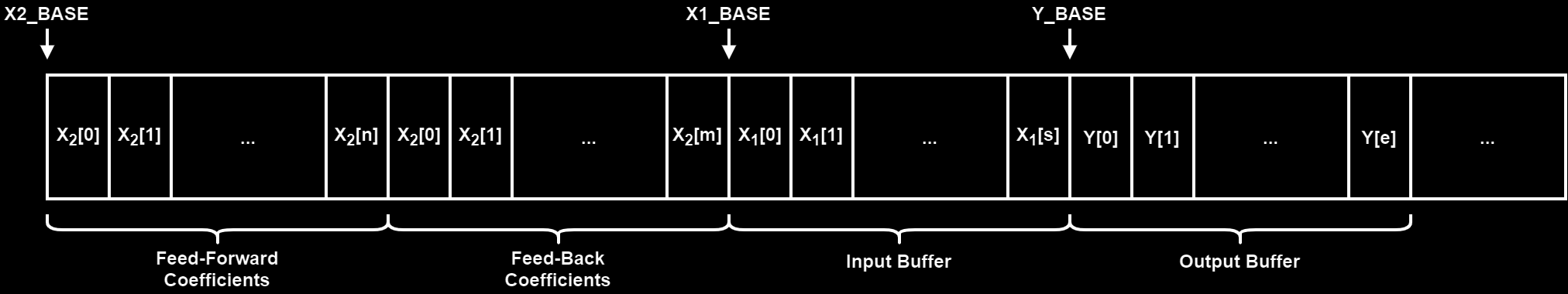
To set-up of the FMAC for a IIR filter is almost identical to the FIR filter case. The only big difference is the way the coefficient memory area is set up, which now has two sections. The coefficients for the feed-forward and the feed-back part are concatenated and written to the $ X_2 $ memory area as follows:
//Load X2 buffer (Coefficient buffer)
LL_FMAC_SetFunction(FMAC, LL_FMAC_FUNC_LOAD_X2);
LL_FMAC_SetParamP(FMAC, n);		//Number of values to be loaded into X2 buffer @ X2_BASE: Feed-forward coefficients (b[N])
LL_FMAC_SetParamQ(FMAC, m);		//Number of values to be loaded into X2 buffer @ X2_BASE + N: Feed-back coefficients (a[N])
LL_FMAC_SetParamR(FMAC, 0);		//Not used
LL_FMAC_EnableStart(FMAC);		//Start FMAC processing

//First the feed-forward coefficients (b)
for(i = 0; i < n; i++) {
	LL_FMAC_WriteData(FMAC, iirBCoeffQ15[i]);	//b[N]
}

//Second the feed-back coefficients (a)
for(i = 0; i < m; i++) {
	LL_FMAC_WriteData(FMAC, iirACoeffQ15[i]);	//a[M]
}
As is discussed in the FIR case, the most efficient way of using the FMAC is with the DMA so only that example will be shown here. The code below is for how to set-up the FMAC for a 4th Order IIR with the DMA writing/reading to/from the FMAC unit:
//Peripheral clock enable
LL_AHB1_GRP1_EnableClock(LL_AHB1_GRP1_PERIPH_FMAC);

//Start with resetting the FMAC Unit
LL_FMAC_EnableReset(FMAC);

uint8_t order = 4;
uint8_t bufferSize = 1;
uint8_t n = order + 1;
uint8_t m = order;
uint8_t postShift = 2;		//Coefficients are in Q2.13
int16_t iirBCoeffQ15[5] = { 40, 159, 238, 159, 40 };		//b[0], b[1], ..., b[N]
int16_t iirACoeffQ15[4] = { -19411, 18957, -8639, 1536 };	//a[1], a[2], ..., a[M]

//Configure Buffer memory base and lengths
//Set the coefficient buffer
LL_FMAC_SetX2Base(FMAC, 0);
LL_FMAC_SetX2BufferSize(FMAC, n + m);

//Set the input buffer
LL_FMAC_SetX1Base(FMAC, (n + m));
LL_FMAC_SetX1BufferSize(FMAC, (n + bufferSize));
LL_FMAC_SetX1FullWatermark(FMAC, LL_FMAC_WM_0_THRESHOLD_1);

//Set the output buffer
LL_FMAC_SetYBase(FMAC, (2 * n + m + bufferSize));
LL_FMAC_SetYBufferSize(FMAC, (m + bufferSize));
LL_FMAC_SetYEmptyWatermark(FMAC, LL_FMAC_WM_0_THRESHOLD_1);

//Load empty values to input buffer (X1)
LL_FMAC_SetFunction(FMAC, LL_FMAC_FUNC_LOAD_X1);
LL_FMAC_SetParamP(FMAC, n);			//Number of values to be loaded into X1 buffer
LL_FMAC_SetParamQ(FMAC, 0);			//Not used
LL_FMAC_SetParamR(FMAC, 0);			//Not used
LL_FMAC_EnableStart(FMAC);			//Start FMAC processing

uint8_t i;
for(i = 0; i < n; i++) {
	LL_FMAC_WriteData(FMAC, 0x00);
}

//Load empty values to input buffer (Y)
LL_FMAC_SetFunction(FMAC, LL_FMAC_FUNC_LOAD_Y);
LL_FMAC_SetParamP(FMAC, m);			//Number of values to be loaded into Y buffer
LL_FMAC_SetParamQ(FMAC, 0);			//Not used
LL_FMAC_SetParamR(FMAC, 0);			//Not used
LL_FMAC_EnableStart(FMAC);			//Start FMAC processing

uint8_t i;
for(i = 0; i < m; i++) {
	LL_FMAC_WriteData(FMAC, 0x00);
}


//Load X2 buffer (Coefficient buffer)
LL_FMAC_SetFunction(FMAC, LL_FMAC_FUNC_LOAD_X2);
LL_FMAC_SetParamP(FMAC, n);			//Number of values to be loaded into X2 buffer @ X2_BASE: Feed-forward coefficients (b[N])
LL_FMAC_SetParamQ(FMAC, m);			//Number of values to be loaded into X2 buffer @ X2_BASE + N: Feed-back coefficients (a[N])
LL_FMAC_SetParamR(FMAC, 0);			//Not used
LL_FMAC_EnableStart(FMAC);			//Start FMAC processing

for(i = 0; i < n; i++) {
	LL_FMAC_WriteData(FMAC, iirBCoeffQ15[i]);
}

for(i = 0; i < m; i++) {
	LL_FMAC_WriteData(FMAC, iirACoeffQ15[i]);
}

//Configure the read/write method
//Write: Polling; Read: Polling
LL_FMAC_DisableIT_WR(FMAC);
LL_FMAC_DisableIT_RD(FMAC);
LL_FMAC_EnableDMAReq_WRITE(FMAC);
LL_FMAC_EnableDMAReq_READ(FMAC);

//Enable Clipping: Values saturate and do not wrap
LL_FMAC_EnableClipping(FMAC);

//Configure FMAC Unit
LL_FMAC_SetFunction(FMAC, LL_FMAC_FUNC_IIR_DIRECT_FORM_1);
LL_FMAC_SetParamP(FMAC, n);				//Number of feed-forward (b) coefficients
LL_FMAC_SetParamQ(FMAC, m);				//Number of feed-back (a) coefficients
LL_FMAC_SetParamR(FMAC, postShift);		//Gain applied to the accumulator output
The DMA configuration is the same as in the FIR case, as is the way of monitoring the operation completion.
Benchmark
This section shows some performance evaluation of the FMAC unit, comparing Polling vs DMA implementation and also comparing it to the ARM CMSIS-DSP Library implementation running on the MCU core. The tests consists on running the filter over a 1024 samples sized array and measure the time it takes to complete. The MCU used is the STM32G473 running at 170 MHz, with the FMAC also running at 170 MHz.
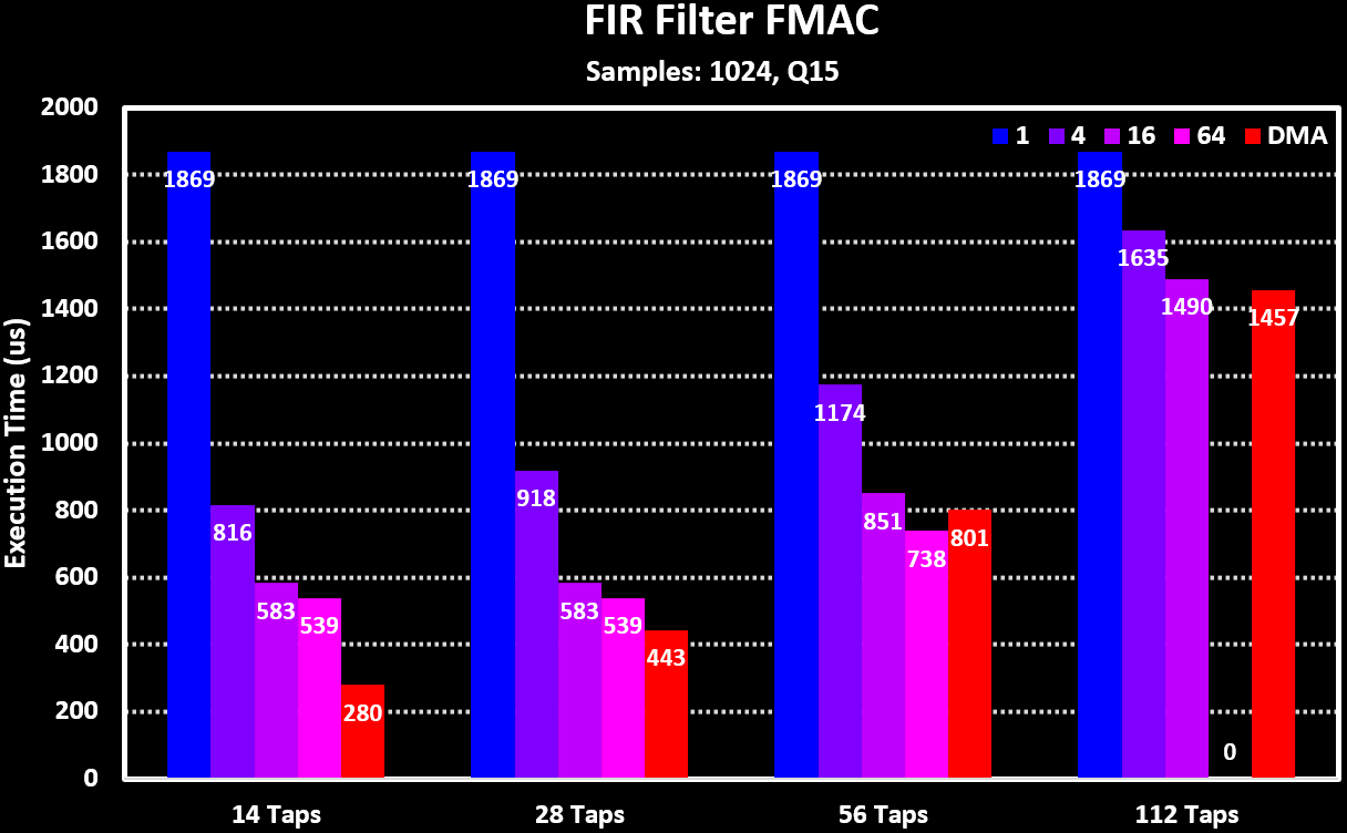
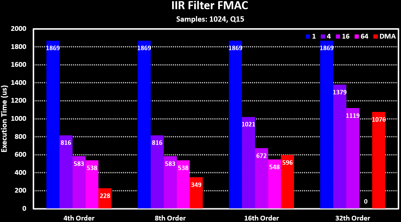
Below is a graph showing some performance numbers of the FMAC for different FIR and IIR filters, both in polling mode with different input and output buffer area sizes as well as when using the DMA. It is very clear that for small buffer sizes the processing time is dominated by read/writing and waiting operations and only when the buffer area is at least 16 samples long the FMAC processing dominates.
For comparing the FMAC performance to running the filters on the MCU Core the ARM CMSIS-DSP library functions are used. The FMAC is running in DMA mode while the ARM CMSIS-DSP functions are using a block size equal to the number of samples (1024) so that both are running with their ideal conditions. Both the normal and the _fast version on the filter functions are used. The results can be seen in the figures below:
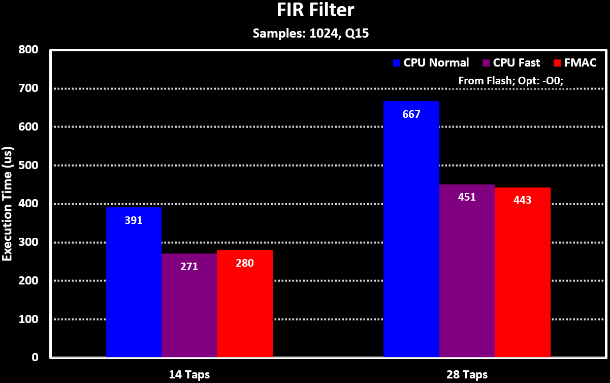
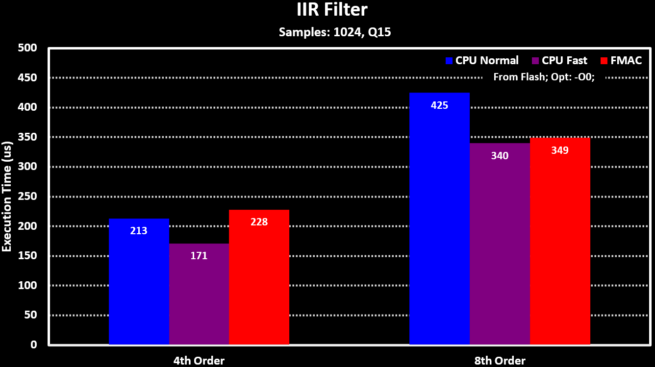
It shows that the FMAC performs on paar with the MCU Core when the equivalent filter function is used, the _fast version which doesn’t have overflow protection. This is expected for this MCU as both the Core and the FMAC run at the same clock rate, but the results can vary a lot when they don’t, which can be the case with higher clocked MCUs like the STM32H723.
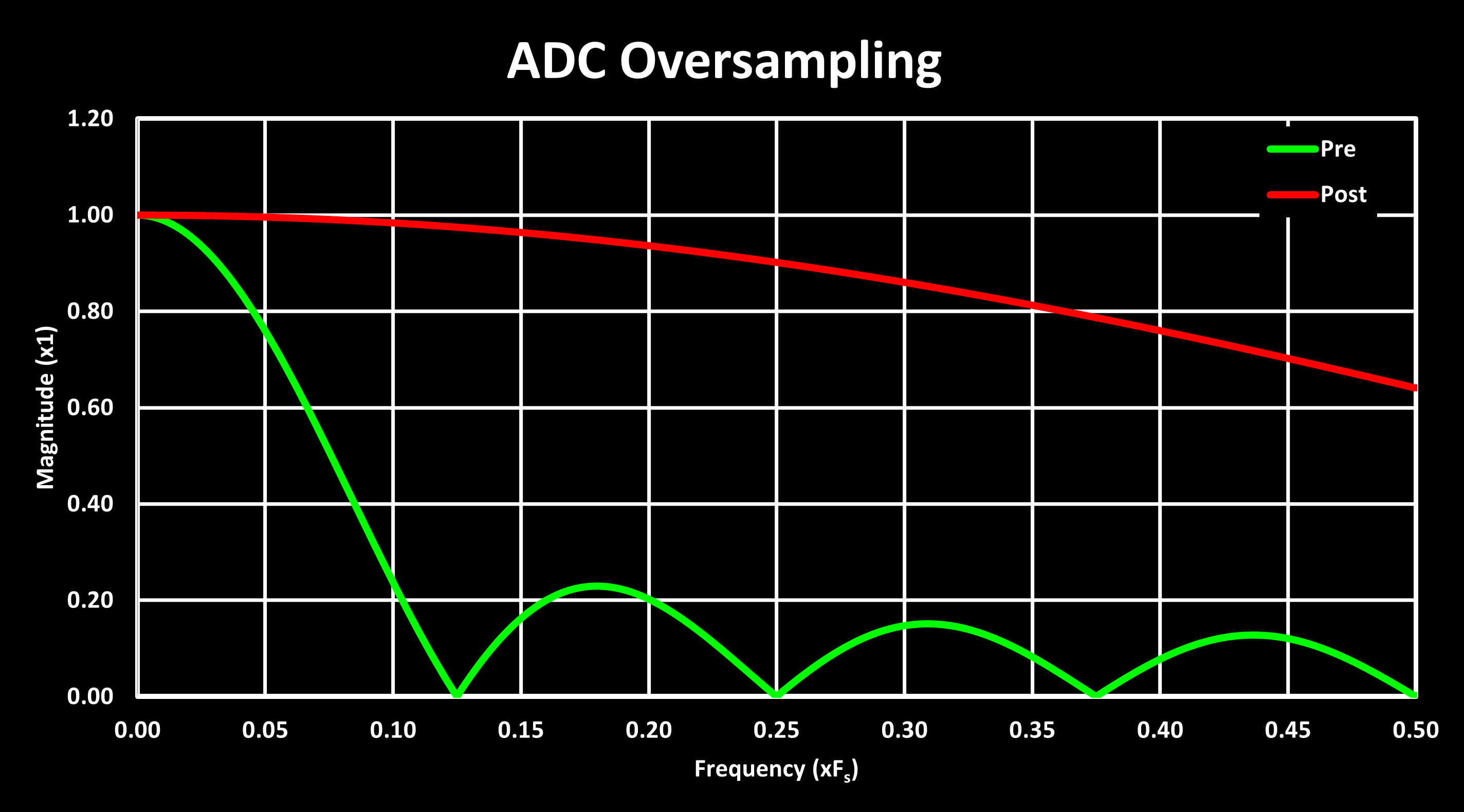
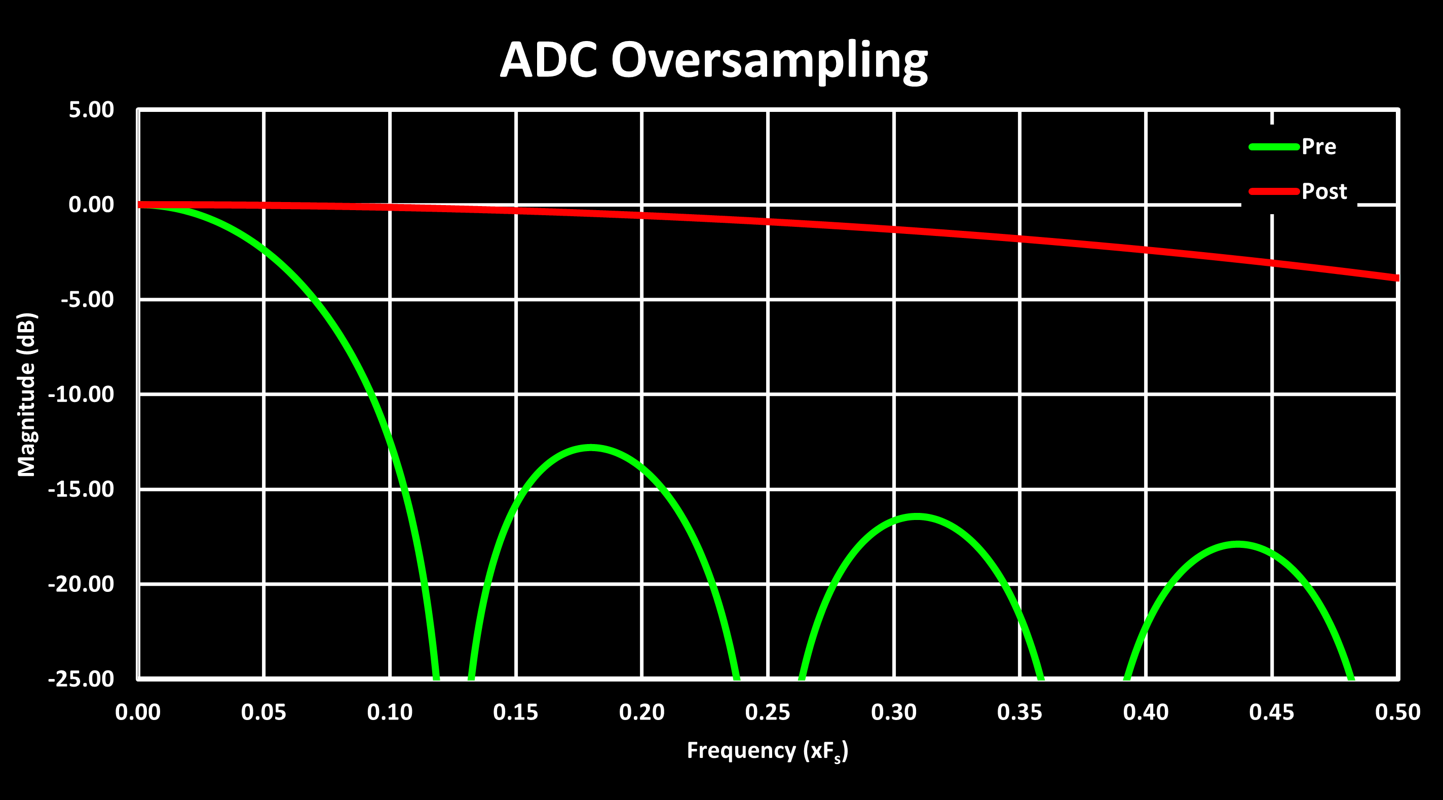
Another useful hardware accelerators is ADC oversampling, which is increasingly being integrated into modern MCUs, in addition to the external dedicated ADCs that have long implemented this feature. Hardware oversampling allows sacrificing ADC sample rate to improve SNR without the computational overhead that software-based oversampling would incur. For each halving of the effective ADC sample rate (doubling the oversampling ratio), the SNR improves by 3 dB, equivalent to a gain of 0.5 bits of resolution (since 1 bit corresponds to 6 dB).
For the specific case of the STM32G4, the hardware oversampling allows for ratios from 1 to 256 in power-of-2 steps, while the newer STM32H7 allows ratios up to 1024. This enables an increase of ADC resolution of up to 4 bits for the STM32G4 and 5 bits for the STM32H7. The oversampling comes at the cost of effective ADC sample rate, reducing it from a maximum of 4 MSPS down to $4 / 256 = 15.6 ksps$ on the STM32G4, and from 3.6 MSPS down to $3.6 / 256 = 3.5 ksps$ on the STM32H7.
The hardware implementation of ADC oversampling in the STM32 is quite simple, its just a summing circuit with an output shift register. Samples corresponding to the oversampling ratio are summed together, and the resulting sum is right-shifted to produce the new ADC sample. Both the oversampling ratio and right shift are programmable. This simple design also makes it easy to use, requiring only a few additional configurations in the ADC setup:
LL_ADC_SetOverSamplingScope(ADC1, LL_ADC_OVS_GRP_REGULAR_CONTINUED);
//For STM32G4:
LL_ADC_ConfigOverSamplingRatioShift(ADC1, LL_ADC_OVS_RATIO_256, LL_ADC_OVS_SHIFT_RIGHT_4);
//For STM32H7:
LL_ADC_ConfigOverSamplingRatioShift(ADC1, 1024, LL_ADC_OVS_SHIFT_RIGHT_5);
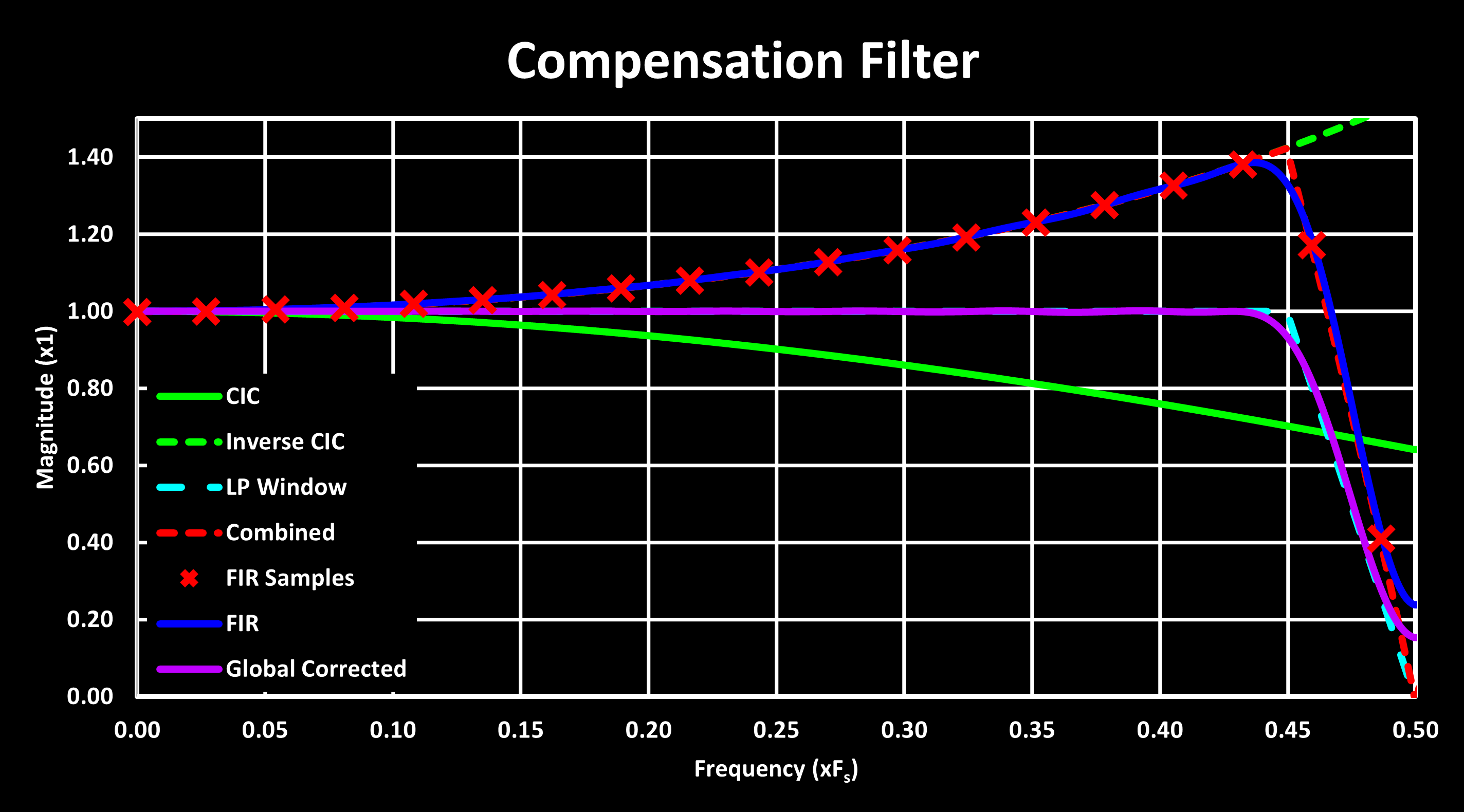
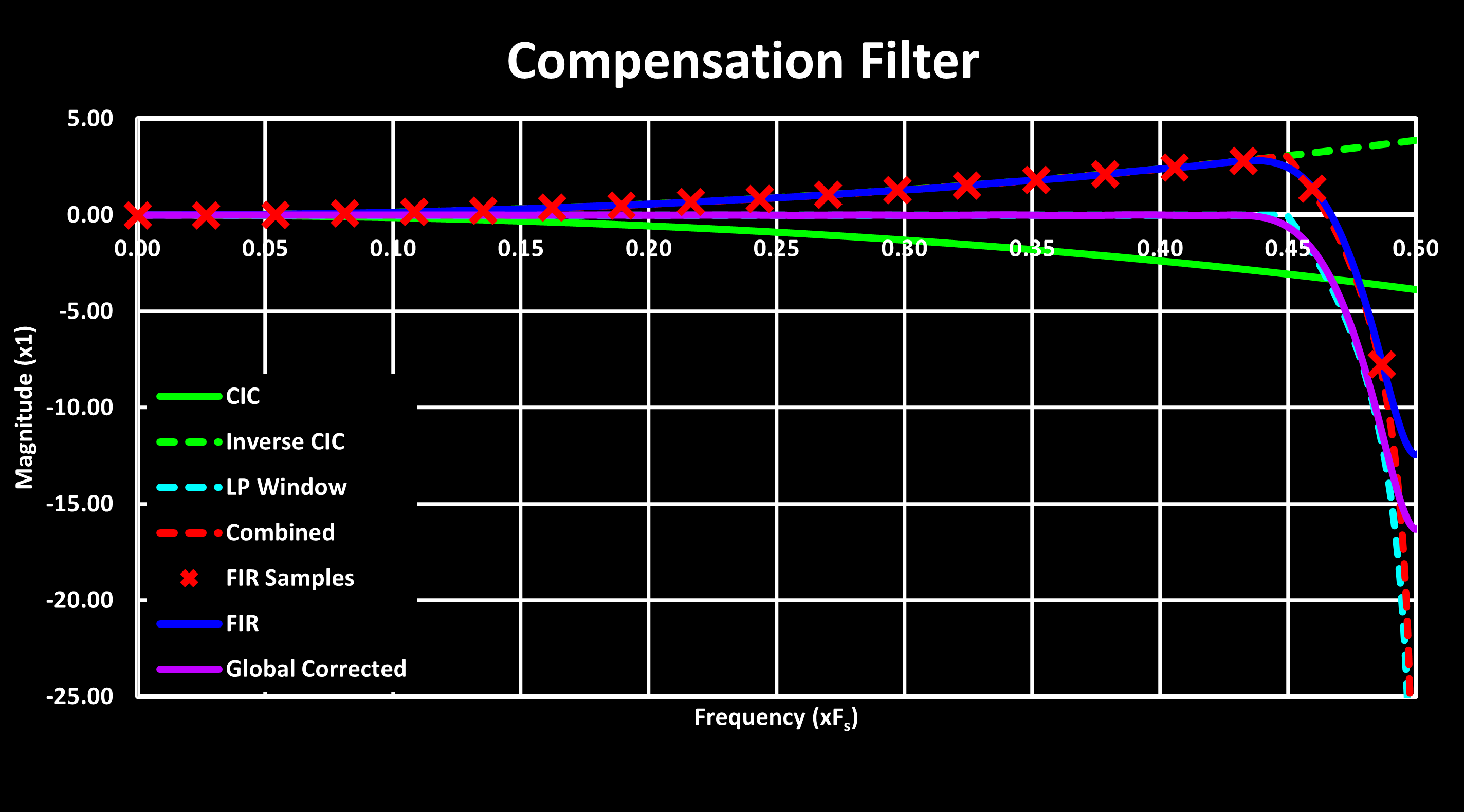
LL_ADC_SetOverSamplingDiscont(ADC1, LL_ADC_OVS_REG_CONT);If the goal is to maintain the original ADC resolution (12-Bits in the STM32G4) and only improve the SNR, the right shift amount should be $log_2(OVSR)$. If the objective is to increase the ADC resolution, the right shift should be $log_2(OVSR \over 2)$. Due to the simple nature of the oversampling hardware, which acts as a moving average filter with decimation, its frequency response is not flat, following a $sinc(x)=sin(x) \over x$ function, the same as a CIC Filter. This is shown in the figure below, both in linear and logarithmic (dB) magnitude scale, and for the response before the decimation (for illustration only) and after decimation (the actual one):
ADC Oversampling Compensation Filter
The one-flat frequency response of the ADC oversampling can be an issue in many applications, and therefore a method to correct this is desirable. One such method is to use a FIR filter with an inverse response to the ADC oversampling, compensating it and creating a flatter passband. This is the same approach used to improve the passband of a CIC filter, explored in CIC Filter page, using the frequency sampling method.
An example of this is shown in the figure below, for a designed compensation filter covering nearly the entire passband, with a cutoff frequency of 0.45 and with 37 coefficients (‘CICCompFilter(8, 8, 0.45, 0.05, 37)').
Ideally, this FIR compensation filter should be implemented in the FMAC unit to offload the whole ADC signal processing from the MCU core. For a single channel, this can be easily accomplished by routing the ADC output register to the FMAC input register using a DMA. If multiple channels are needed, a buffered approach is required, where the FMAC is reused for each channel. The following steps outline this process:
- Connect the ADC to a “double buffer” through DMA with half and full transfer flag IRQ enabled.
- On the first ADC channel IRQ trigger, prepare the FMAC by preloading its X1 buffer with previous samples of the ADC channel.
- Start the FMAC with a DMA feeding it the ADC channel buffer half, and another DMA writing the output to a buffer.
- When the FMAC processed the whole buffer, check if another ADC channel buffer needs processing. If so, repeat the process from step 2.