
The Mini Optical Filter Wheel is a low-cost, compact device for switching between eight 8x8mm optical filters. It is designed around the use of small square filters, which are significantly more affordable than traditional round threaded optics, making it a practical choice for low-budget spectral imaging and other optical experiments. This makes optical filter based Spectral Imaging significantly more affordable and accessible to makes, students, and hobbyist interested in exploring with this technology.
At the core of the system is a custom-designed controller board based on an STM32 microcontroller, paired with a miniature 8 mm stepper motor and a magnetic encoder for precise, reliable positioning of the filter wheel. The board supports both I2C and UART interfaces for easy integration with platforms like Arduino or Raspberry Pi. Optional trigger in/out lines enable for synchronized operation with camera shutters or flashes, such as with the Multispectral Illumination project.
Features
- Filter Format: Supports standard 8x8mm square optical filters
- Compact Design: Small footprint fits tight optical setups
- Materials: 3D-printable parts, affordable components
- Accurate Positioning: Magnetic encoder with 14-bit resolution
- Open Hardware: Fully documented design with printable and source files
- Flexible Control: I2C and UART interfaces for microcontroller integration
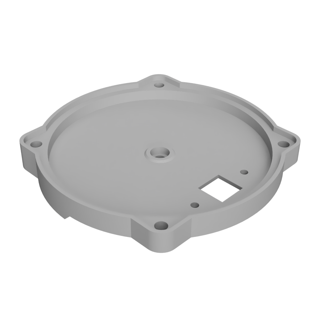
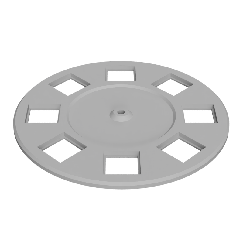
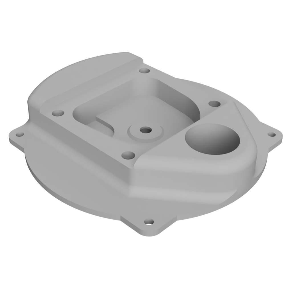
Below is an exploded view of the filter wheel with all the mechanical parts, without the screws or and plastic inserts, visible. The filter wheel and case is 3D printed (grey parts) and is assembled together with M2 screws. The step files for these parts are available to download in the Parts section. The other mechanical parts, bearings, gears and screws, are easily found on eBay and/or AliExpress and are also listed in the Parts section.
Parts
As mentioned and can be seen in the section above, the filter wheel structure is made from 3D printed parts assembled together with M2 screws into M2 inserts. In addition to those, some mechanical parts and electronics, have to be acquired. Below is the full parts list, both the 3D printed parts (.stl files) and not.
3D Parts
All 3D printed parts are optimized to reduce overhangs and size, preference was given in splitting parts up to facilitate printing. For the shown (my) filter wheel, the parts were 3D printed in PLA giving the parts great rigidity. Other plastics can also be used, like ABS or PETG.
As part of a partnership with PCBWay (they sponsored the PCB), these 3D parts can be ordered directly from them: Filter Wheel Controller Board.
Mechanical
List of all none 3D printed mechanical parts required for the filter wheel:
- Shaft (x1): About 12 mm long and 2 mm diameter metal shaft
- Bearings (x2): 682zz with 2 mm inner diameter and 5 mm outer diameter
- Magnet (x1): Either a 4x1.5 mm or a 2x2 mm diametrically magnetized disc magnet
- Large Gears: A 46 teeth modulus 0.5 plastic gear with a inner diameter of 1.95 mm (tight fit on the 2mm rod)
- Small Gears (Pinion): A 8 teeth modulus 0.5 plastic gear with a inner diameter of 0.8 mm (tight fit on the stepper shaft)
- Screws: Assortment of four M2x4 mm and four M2x6 mm screws and eight M2 (OD 3.5 mm, Length 3 mm) metal inserts
Optical
List of (compatible) optics components:
- Optical Filter: Custom selection of 8x8 mm optical filters with thicknesses up to 1 mm
- Camera Module: Any camera module with a M12 mount (has to be removed) with 18 mm screw spacing
- Lense: Any M12 lense
Assembly
The filter wheel is designed for easy assembly, with the steps outline below:
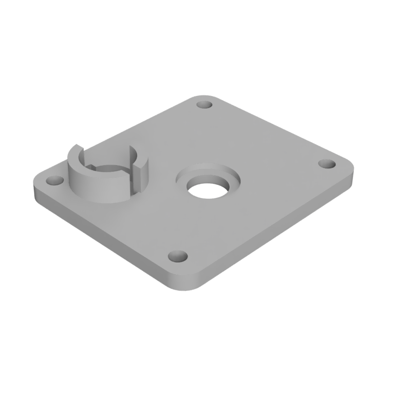
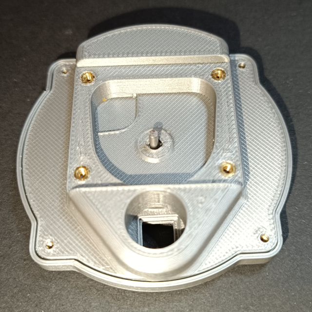
Step 1: Prepare top and bottom parts
The first step is to insert the M2 metal inserts (red circles), 4 into the filter wheel bottom and 4 into the filter wheel top. Use a iron set to around 200 ºC and push them (almost no force should be required) into there respective holes.
Next the two 682zz bearings (blue circles) have to be press fitted. One into the center of the filter wheel bottom piece and one into the center of the filter wheel top piece (from the bottom).
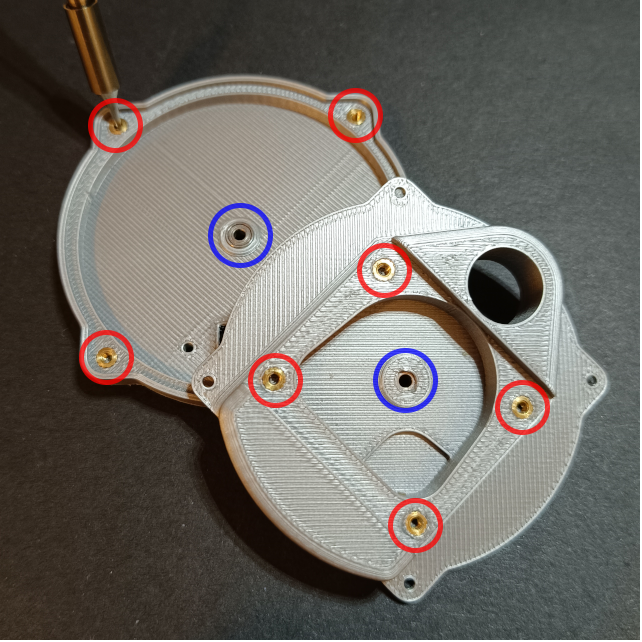
Step 2: Prepare filter wheel
The individual 8x8 mm optical filters fit loosely into the cutouts in the wheel and have to be glued in place.
Depending on how permanent the optical filters should be mounted, use epoxy glue (permanent) or water solvable wood glue (temporary). Put a tiny drop of the glue on two opposite corners of the filter, preferably use a toothpick to dose and place the glue.
Step 3: Add filter wheel
With the individual parts prepared, the filter wheel is placed into the bottom part
Now the shaft is slowly pushed through the filter wheel center until it reaches into the bearing in the bottom part.
Step 4: Enclose filter wheel
Next the top part is added, with the rod going through the bearing, enclosing the filter wheel.
After making sure the filter wheel can spin freely and fix the top to the bottom part with 4 M2x4 screws.
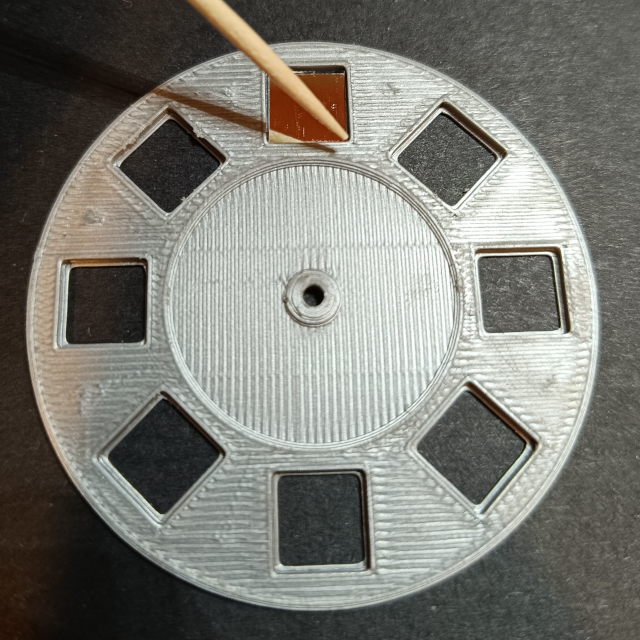
Step 5: Add main gear
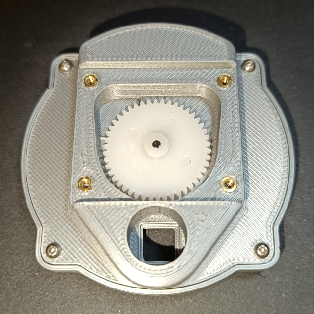
Either glue the magnet for the encoder to the top of the main gear or insert it into it.
Then push the main gear onto the rod coming from the filter wheel. Make sure the main gear goes all the way, until seated on the bottom part elevation. It may be necessary to push the rod further through the filter wheel and bottom part, if it goes out of the bottom part it may need to be trimmed slightly.
Step 6: Assemble motor mount
Now the motor mount is assembled. First slide the motor controller PCB to the motor mount piece, it should have a tight fit. Then take the mini stepper motor and insert it into its position. This is a very tight fit and may require some sanding. The motor bushing should be flat with the bottom of the motor mount. Add the pinion gear to the motor shaft, making sure to leave a gap between the motor mount and the gear.
Finally, either solder the motor wires to the motor controller PCB or crimp a JST-GH connector to the leads and plug it in.
Step 7: Add motor mount
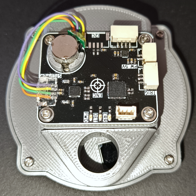
The final step is the position the assembled motor mount, with the controller PCB and stepper motor and pinion, onto the top filter wheel case piece. With it in place, secure it to the top piece with 4 M2x6 screws.
This concludes the assembly, making sure that the stepper motor can spin the filter wheel, and then calibrate the 0 position of the filter wheel in software.
Version History
Revision 2
Schematic: Filter_Wheel_Controller_Schematic_V2.pdf
Gerber: Filter_Wheel_Controller_Gerber_V2.zip
This is the second version of the custom filter wheel controller. The first version had a few major mistakes in the PCB such as the wrong footprint for the encoder (pitch of 0.5mm instead of 0.4mm), unconnected test pin of the encoder (which MUST be connected to ground), and unconnected enable of the LDO. The Revision 2 PCB was kindly sponsored by PCBWay, and as part of this partnership it can be ordered directly from them: Filter Wheel Controller Board.
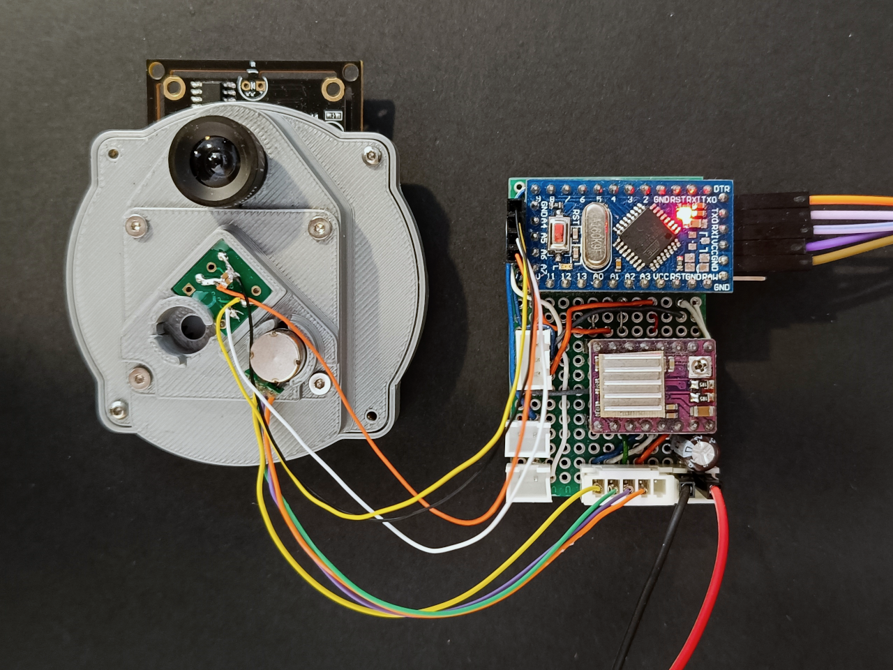
Prototype
The proof-of-concept prototype of the filter wheel control board reused the Arduino Pro Mini based stepper controller originally used in the Linear Actuator project. As here the stepper is a much smaller (8 mm diameter) stepper, the stepper driver (DRV8824) is supplied with the lowest supported voltage (8 V) and its the drive current limit reduced to approximately 100 mA. A magnetic encoder, the AS5600, is connected over the I2C interface and mounted to a SOIC-8 breakout board. The Arduino prototype is controlled via UART. The figure below shows this early prototype:
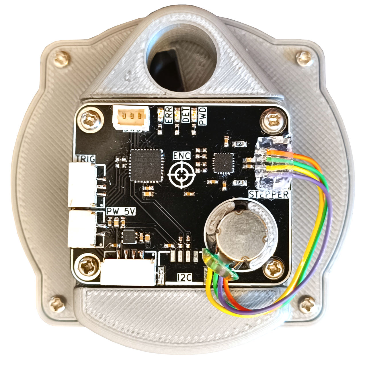
Overview
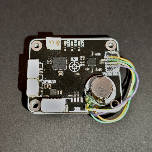
The final filter wheel controller board is built around the STM32C092, a tiny, low-cost MCU from STMicroelectronics. The board is responsible for driving the 8 mm stepper motor and for reading the magnetic encoder to track the wheel’s position precisely. It is designed to fit the filter wheel case, with a motor cutout for tighter integration. The board measures just 30x36 mm. Power and communication are provided via I2C or UART connectors. Additional trigger I/O interfaces allow for synchronization with a camera shutter or flash.
Below is a view of the motor driver board with the location of all the different blacks/ICs:
Power Supply
The power supply of the controller board is minimal, consisting of a single 1 A LDO, the TLV76733, providing a 3.3 V rail for the MCU and logic. Power can be supplied from either the dedicated connector or through either of the communication connectors (I2C or UART). they all are connected in parallel and to the LDO. All power lines are connected in parallel and feed both the LDO and the stepper driver. The stepper motor receives power directly from the input voltage, no regulation is performed. For the 8 mm stepper used here, 5V is recommended.
MCU
The chosen MCU the STM32C092, part of ST’s new C0 series. It runs at up to 48 MHz and is based on the ARM Cortex-M0+ core. This MCU was chosen for its simplicity, low cost and for being available in very small from factor packages such as the used 32-Pin QFN variant. The MCU communicates with the magnetic rotation encoder via an SPI interface. It controls the stepper driver through a UART connection and a set of STEP and DIR digital output lines.
Interfaces
Two digital communication interfaces are provided on the controller board. An I2C interface, considered the primary interface, and a UART interface. In addition to the digital interfaces, there is a dedicated synchronization interface that includes trigger input and output pins for coordinating with external devices such as camera shutters or flash controllers.
All interfaces operate at 3.3 V logic levels and connect directly to the microcontroller without any level shifting. The board also includes a debug interface for firmware development, using SWDIO. This interface is intended for use with spring contacts, though an optional 1.27 mm header can be soldered in place.
Stepper Driver
The stepper driver used is the TMC2300, a modern and programmable driver from Analog Devices. It has integrated power MOSFETs and can drive stepper motors with up to 1.2 A RMS. Most importantly for this application, it operates on supply voltages as low as 2 V and up to 11 V, making it a perfect choice for driving the small 8 mm stepper motor at the recommended 5 V. This was not possible with the DRV8825 used in the prototype, which required a higher minimum voltage (8 V).
Beyond that, the TMC2300 offers a full suite of advanced stepper control features. It supports microstepping up to 256 steps, silent stepper operation, automatic current scaling, and stall detection. The driver can be configured and controlled over a UART interface, or operated in standalone mode. To support all features, the stepper is connected to the MCU over a UART interface besides the STEP and DIR control lines. The maximum current limit of the driver is programmable but can, and should, also be adjusted through the external current sense resistors. Here the sense resistors are set to 2 Ohm, limiting the maximum current to approximately 100 mA.
Magnetic Rotation Encoder
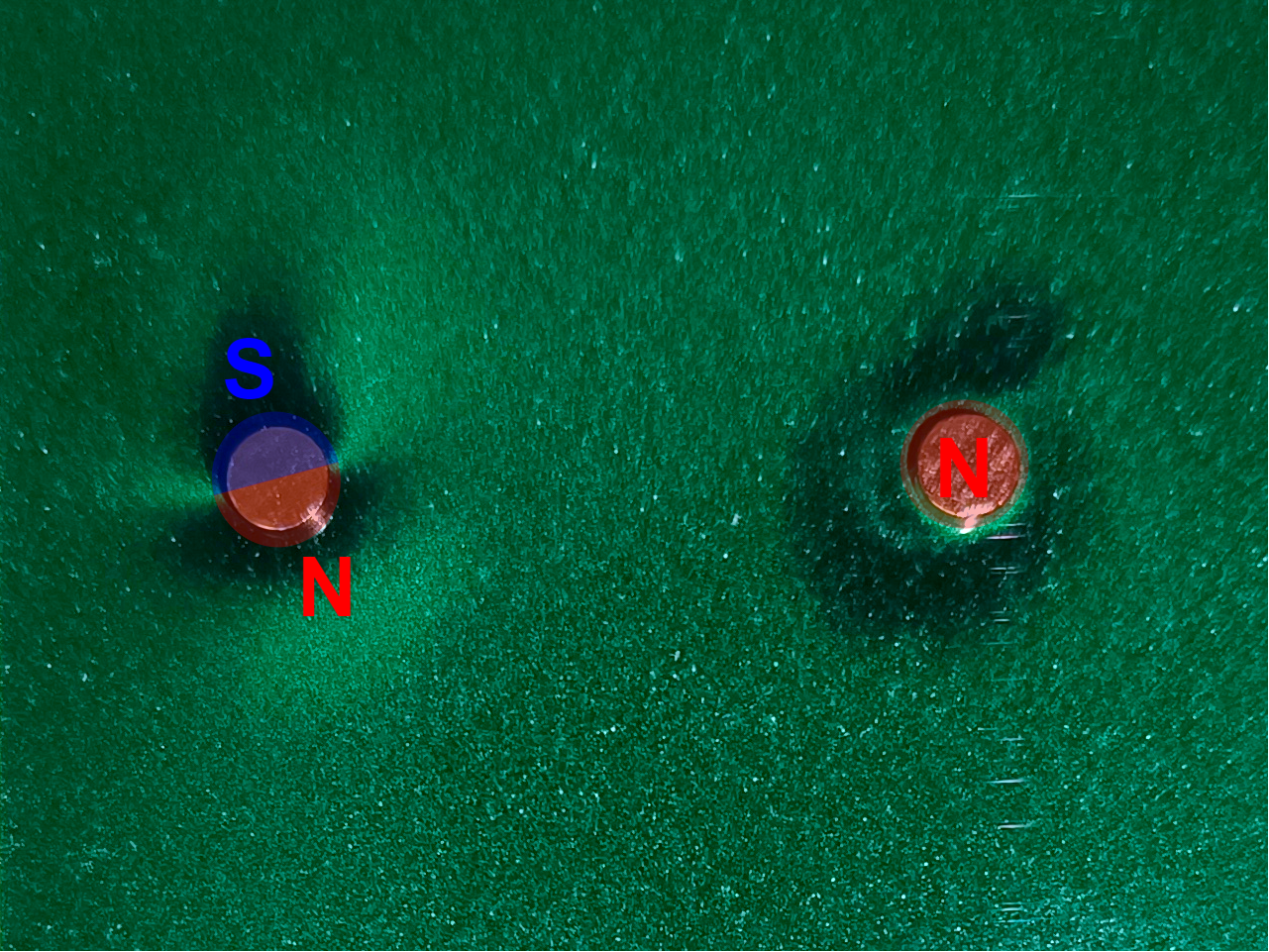
To detect the absolute position of the filter wheel, the MA732 magnetic encoder is used. It connects to the MCU via SPI and provides 14-bit angular resolution (down to under 0.1 degrees) and update rates up to 1 kHz. Magnetic rotation encoder, like the MA732, require diametrically magnetized disc magnet (not the more common axial type). In a diametric magnet, the north and south poles are on opposite sides (on the left), not top and bottom (on the right). This is shown in the figure below:
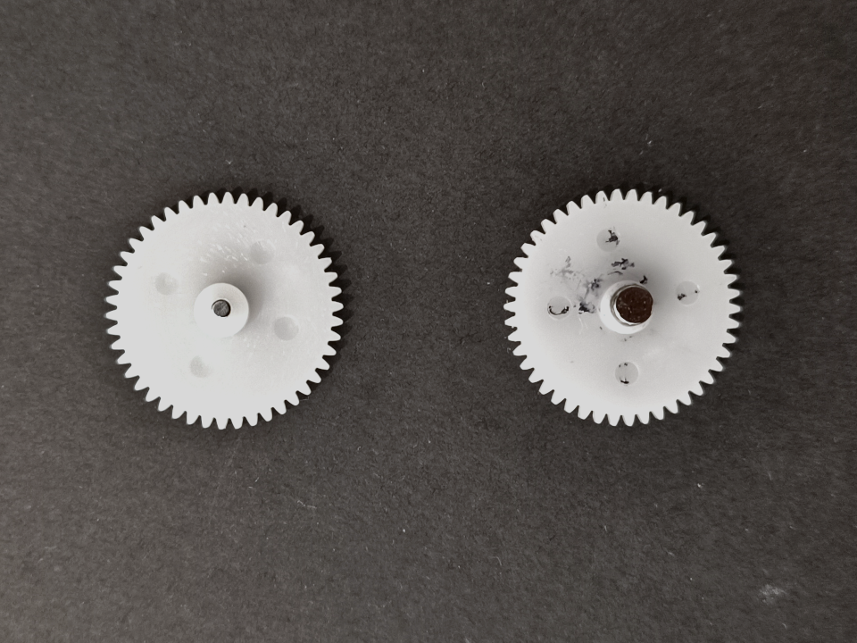
Two magnet sizes were tested: a 2x2 mm disc that fits inside the main gear, and a 4x1.5 mm disc that has to be glued on top, as illustrated in the figure below. The smaller magnet, fitted into the gear, keeps the height compact but creates a less secure fir with the shaft. The top mounted magnet leaves more space in the gear for a secure fit of the shaft but adds 1.5 mm to the total height.
Prototype
As described in the hardware section, the initial prototype uses an Arduino Pro Mini (ATmega328p). The firmware was developed using the Arduino IDE and is available for download here: FilterWheelController.ino .
The prototype communicates over a UART interface at 115200 baud, using 8-N-1 mode. The controller responds to simple single-letter ASCII commands, as listed below:
- Step (“S;"): Moves the wheel a single step. This does not correspond to a full slot, and is used for calibration when aligning the first slot.
- Next (“E;"): Rotates the wheel forward by one full slot.
- Previous (“Q;"): Rotates the wheel backward by one full slot.
- Rotate (“R;"): Enters continuous rotation mode until interrupted by another command.
The prototype also periodically reports its status as “E: <angle> S: <steps> R: <rotation_flag>”, where “<angle>” is the current angle (0-4096), “<steps>” are the remaining steps to reach target position and “<rotation_flag>” shows the continuous rotation mode status.
Calibration Tip
To calibrate the wheel’s starting position (slot 0), use the “S;” command to manually align the first filter. Note the reported angle (E: xxx) when properly aligned, and then update the firmware by setting that value in the
int zeroAngle = xxx;Custom Board
As described in the hardware section, the custom board uses the STM32C092 microcontroller, and therefore for simplicity the firmware was developed using the STM32CubeIDE. It mostly uses the Low Level (LL) HAL from STM and custom drivers to interface with the absolute magnetic encoder and stepper motor driver. The current version only supports the UART interface for controlling the filter wheel and relies on the same commands as the prototype version.
The full firmware is available on Github: Mini Optical Filter Wheel
TBD