This project was developed initially during the NXP HoverGames3 as part of the AutoSQA project, and with the objective of adding wheel odometry information to the NXP Mobile Robotics Buggy3 Kit (MR-Buggy3). This kit includes the NXP FMUK66, a Robotic Drone Vehicle/Flight Management Unit (VMU/FMU) running the PX4 Autopilot, and therefore a custom driver to integrate the developed wheel encoder into the PX4 firmware was also developed, as a part of this project.
In general, this project consists of the Wheel Encoder Acquisition board, a acquisition board for up to 4 HAL sensors (S49e) that counts pulses generated by a magnet passing over these HAL sensors, the firmware for it and the driver to integrate it into the PX4 autopilot. And also the necessary hardware, 3D printed holders, to mount the necessary HAL sensors to the MR-Buggy3 (which uses the WLToys 124019 RC buggy) inside the wheel cavities facing its wall. This project encompass therefore a complete solution for adding wheel odometry to the NXP MR-Buggy3, or other mobile robotics platforms that use the WLToys 124019 chassis and derived chassis from it (e.g. the WLToys 124018). It can also be used for adding wheel odometry to other platforms, by developing custom HAL sensor holders. In theory other sensors can also be used, as long as they can be powered from 5V and output a analog signal that can be digitized with a simple comparator.
Version History
Revision 1
Schematic: Wheel_Encoder_Schematic_R1.pdf
Gerber: Wheel_Encoder_Gerber_R1.zip
This is the first version of the custom Wheel Encoder Acquisition board. There are some small hardware mistakes in this version:
- The debug header has the pin order reversed in comparison to all other headers. POWER and GND are switched and if the same cable is used then for the interfaces it can lead to burn-down of the board if the connection is not reversed! Also, on the debug header, the POWER pin is connected to the internal 3.3V, and not to the VIN (5V). Due to this mistakes, it is preferable to not use the POWER pin of the debug connector and instead power the board through one of the interface connectors.
Prototype
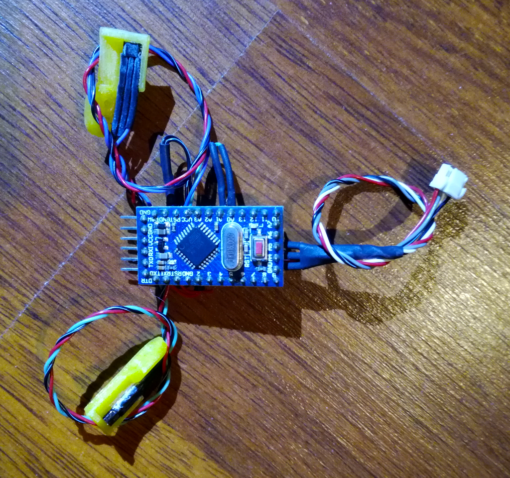
The first version, proof of concept prototype, of the Wheel Encoder Acquisition board was simply an Arduino Pro Mini with the HAL sensors (S49e) connected directly to the analog inputs, with the comparator (trigger) done in software. The interface used for the Arduino Prototype is I2C, and it is still compatible with the developed PX4 driver. This prototype can easily be replicated, only requiring S49e HAL sensors and an Arduino Pro Mini. The figure below shows this prototype:
Overview
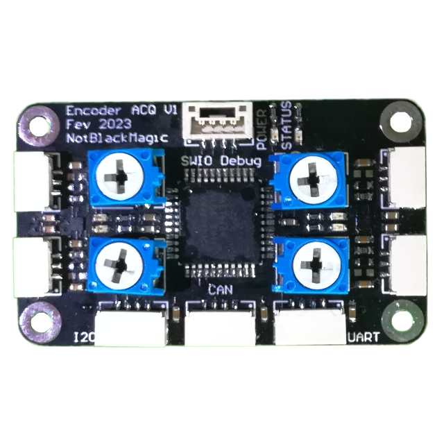
The Wheel Encoder Acquisition board is built around the NXP MKE16Z64VLD4 MCU, one of the simplest MCUs with a CAN interface. The developed acquisition board has 4 sensor inputs for HAL sensors like the S49e, on 4 3-Pin JST-GH connectors. Each of these inputs connect to a septate voltage comparator (NCX2220) to convert the sensor voltage to a digital signal, a pulse. The voltage comparator circuit has adjustable threshold, through the potentiometers, and hysteresis, through a resistor (default value is 5% hysteresis). The output of the voltage comparator is connected to both a LED, for visual feedback, and to the MCU to interrupt enabled GPIOs. This signal conditioning circuit is shown in the figure below:
The board has connectors for three different interfaces, UART, I2C or CAN, with the CAN interface using an advanced SIC CAN transceiver chip from NXP, the TJA1463. Each of these interfaces connect to the onboard LDO through a shotkey diode, and therefore the board can be powered from any of these interfaces, as long as the supplied voltage is 5V (directly use to power the HAL sensors).
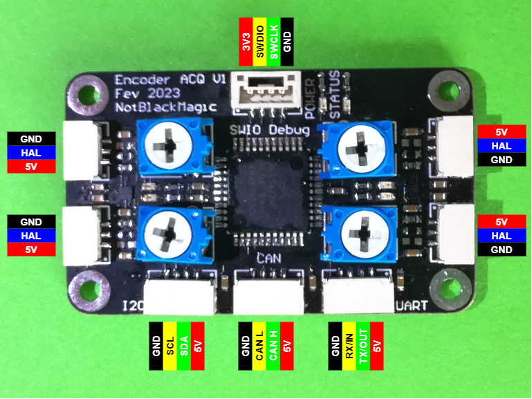
See below for the pinouts of each of the JST-GH connectors, with the sensor connectors on the left and right, the interfaces connectors on the bottom and the debug connector at the top (attention here that the debug connector has the POWER and GND pins flipped and only supports 3.3V supply!):
Assembly and Calibration
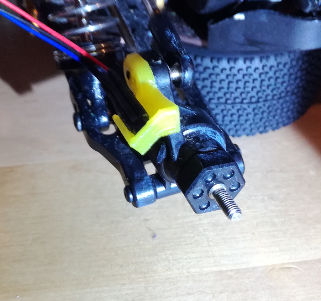
As seen before, this wheel encoder uses a HAL sensor that detects magnets passing over it. These magnets are added to the inside of the wheels, while the HAL sensor is mounted facing towards the inner wall of the wheel. The HAL sensors are mounted this way with the help of 3D printed holders. Two different holders are used, one designed for the front wheels and another designed for the back wheels. The holder for the front wheels is clipped onto the steering arms, while the back holders are screwed directly to the back wheel cups holder. See the figures below to see the mounting of both the front, on the left, and back, on the right, HAL sensor holder:
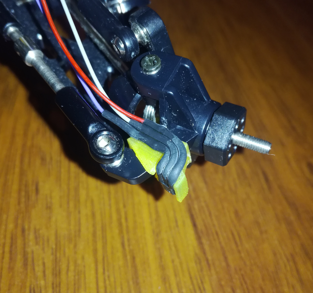
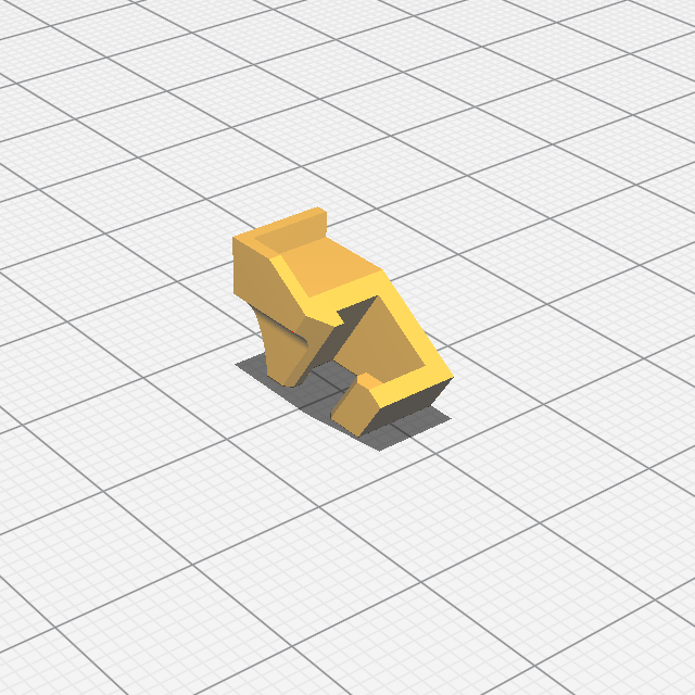
Both holders are designed to be easily 3D printed, without requiring support structures. Ideally they should be printed with a slightly elastic material like PETG (what I used) or ABS instead of inelastic ones like PLA. This is specially important for the front holders, as they clip onto the steering arm and therefore must flex a bit. The back holder is printed with the long side facing down while the front holder should be printed in the following orientation, how it was designed to avoid supports:
After 3D printing the holders, the HAL sensor with soldered on wires and terminated in a 3-Pin JST-GH connector, are glued to the holders face up. I recommend using an epoxy based glue but super glue also works. The HAL sensors are glued into the corner of the holders, as can be seen in the figures above. After that, the holders are mounted to their respective location. The front holders are clipped to the steering arms while the back are screwed to the wheel cup holder, again as can be seen in the figure above.
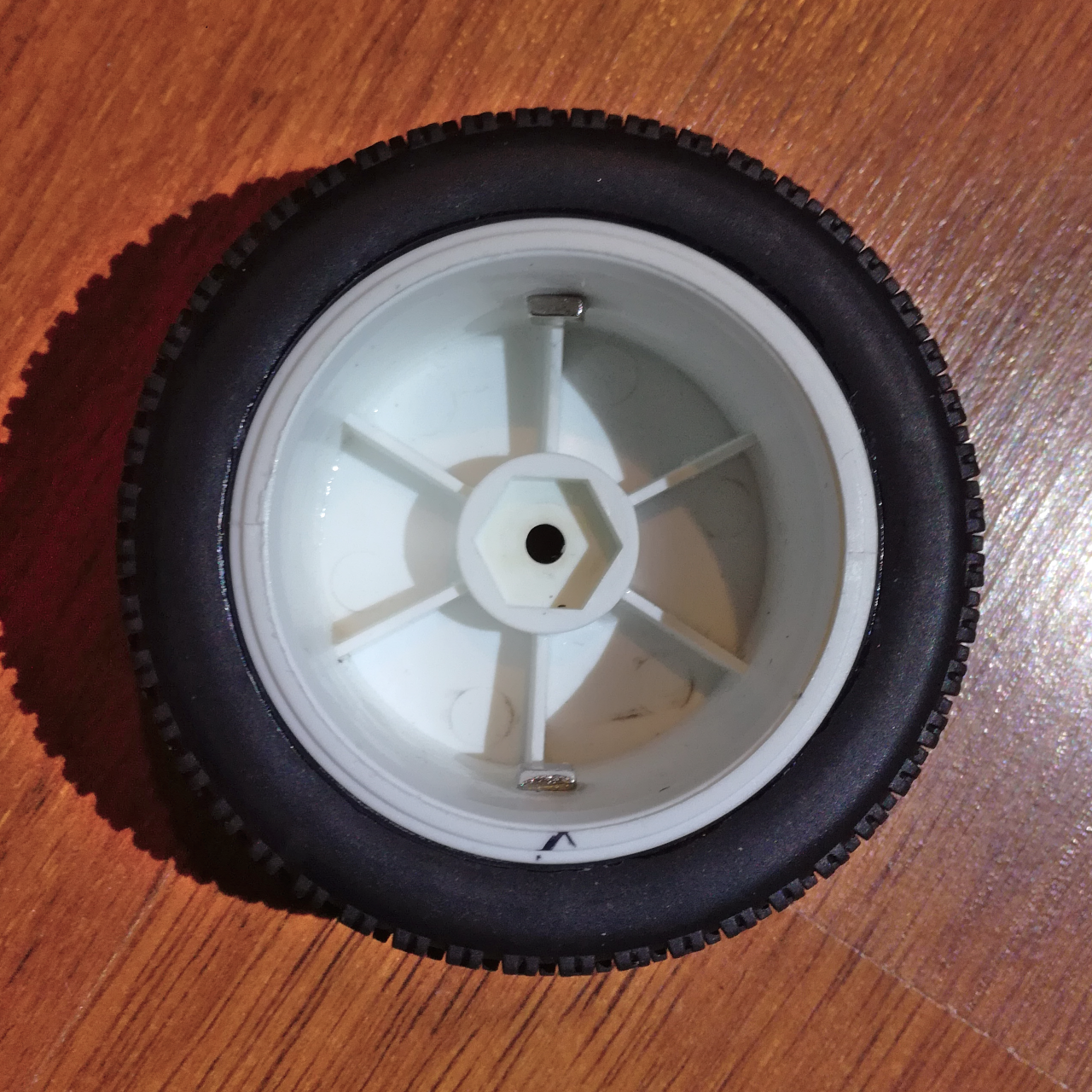
Glue at least one magnet, preferably two or more for increased encoder resolution, to each wheel. The recommended magnet is a 5x5x2 mm neodymium magnet and they should be glued to the wheel using an epoxy based glue, super glue also works but is less reliable. Glue each magnet to the wheel with the same pole facing inwards, it is not relevant which pole just that all the magnets in a wheel face the same pole inwards. See the figure below as reference on how two magnets are mounted to the back wheel, on opposite sides for balancing:
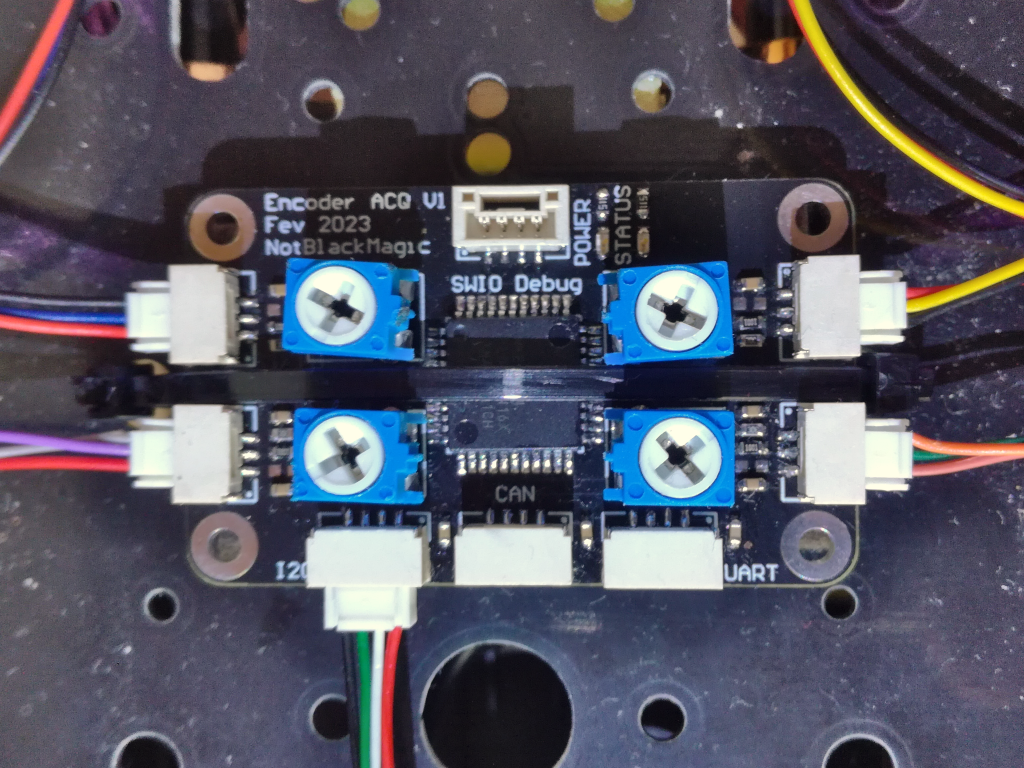
After that, the wheels can be mounted back to their shafts, the HAL sensors connected to the acquisition board and acquisition board connected to the flight/drive management unit e.g. on the FMUK66 to the I2C/NFC port. With everything connected, and the acquisition board powered, the trigger level can be adjusted with the potentiometer. It should be trimmed in a manner that whenever a magnet passes over the HAL sensor, the LED turns ON/OFF. Depending on the magnet pole facing the sensor, it either turns the LED OFF when passing over the sensor or it turns the LED ON.
Find below the 3D files (stl) for the holders, both the front and back, and for either sides, left and right.
3D Files (.stl): HAL_Sensor_Holder.zip
The firmware for the Wheel Encoder Acquisition board is quite simple, reading the conditioned (digitized) sensor signals and providing the acquired values over some digital interface (UART, I2C and CAN). In the current firmware, each level change on the comparator output triggers a GPIO interrupt and the respective wheel encoder tick count is incremented. The RPM value for each wheel is computed periodically based on the change of the respective encoder tick count during this period. In the future a more advanced RPM calculation will be implemented, where the time between successive interrupts is also taken into account, for increased RPM accuracy/resolution.
Also, the current version is uninformed of the wheel rotation direction, only taking positive values. This can be changed in the future by combining two sensor input channels together, the so called High and Low channels for each side, with the sensors offset from each other but reading the same wheel, forming an I/Q (quadrature) encoder setup. This will reduce the number of independent wheel encoder readings from 4 down to 2. Another method to get the wheel rotation direction would be to read the control signal to the motor, and infer the wheel rotation direction from that. This is less accurate, as there is not always a direct connection between the two e.g. the motor rotation direction can lag the control signal due to rotation inertia.
The full firmware is available on Github: Wheel Encoder
As seen in the hardware section, a simple prototype was developed using an Arduino Pro Mini, and which is still compatible with the PX4 driver. The developed code, firmware, for this prototype can be downloaded here: MotorEncoder.ino
Also, to test the I2C connection without the PX4 driver in the mix, a simple Arduino code was developed to read encoder data from the acquisition board and write them to the serial port. This code can also be downloaded here: EncoderReceiver.ino
Interface
This section explains how each of the available interfaces, UART, I2C and CAN, are intended to be used and how to interface with them. The CAN interface is not yet implemented/used.
UART
The UART interface uses the standard 8-N-1 format and a baudrate of 115200. It is mainly used to monitor the Wheel Encoder Acquisition board, it outputs the read encoder tick counts periodically (every 1000 ms) in ASCII format: “LH: %d, LL: %d, RH: %d, RL: %d\n”. The output is synchronized with the status LED blinking.
I2C
The main interface used to get data from the Wheel Encoder Acquisition board is the I2C interface, at least until the switch to CAN is completed. The device acts as an I2C slave with an I2C address of 0x02. The data can be accessed through read commands from the following “registers”, data is returned as most significant byte first (MSB):
| Register | Address | Size | Definition |
|---|---|---|---|
| ID | 0x00 | 1 | ID of the device (‘N’) |
| DATA | 0x01 | 12 | Encoder data (Counts and RPM) |
| PPR | 0x02 | 2 | Pulse per revolution |
The ID register returns a single byte, containing the ID of the device (‘N’). The DATA register returns up to 24 bytes, 6 bytes per wheel in the following order (based on the sensor connector names): Left High, Right High, Left Low, Right Low. Each wheel data is composed of 2 data fields: the encoder tick count in the first 4 bytes and the RPM value in the second 2 bytes. Depending on how many sensors, wheels with encoders, are connected/used, the necessary number of bytes can be read from the DATA register. Finally, the PPR register returns the number of ticks per revolution, in 2 bytes, programmed into the Wheel Encoder Acquisition board and which is used for the internal RPM calculations.
CAN
Not implemented yet.
PX4
As mentioned before, I developed a driver for this wheel encoder for the PX4 autopilot system. The driver is very simple, reading periodically (10 Hz) the encoder values from the wheel encoder over the I2C interface and publishing them as a standard WheelEncoders.msg uORB message. The same firmware also adds a MAVLink message containing the wheel encoder information to the available link defines. This wheel encoder driver is not enabled by default, and the following command must be added to the SD Card file at /etc/extras.txt so that it is run on startup:
set +e
encoder start -X 1
set -e
At the moment their is no further integration of the wheel encoder information into the PX4 autopilot, but I have planned to integrated it into the rover position and velocity controller.
This PX4 Autopilot fork, based on the Beta V1.14 version, is available on my Github: PX4 Autopilot
To see the whole system working, see the video I created on YouTube: https://youtu.be/qfiv8_sycEg