Important Notice
The full Sub-GHz transceiver (the AX series) range of products from OnSemi have been discontinued, with end-of-life scheduled for december of 2022: Official Notice
This includes the transceiver used here, the AX5043, and all others from the same family, the AX5243 and the new AX5045 as well as the SoC (MCU+RF) versions of them, the AX8052F143 and the new AXM0F343.
The VUHF M.2 module is based on the VUHFRadio module, with very similar hardware, but adjusted to fit the M.2 2230 Key E form factor (22x30mm). It was developed specifically to fit the M.2 module holder of the MIMXRT1060-EVKB development board from NXP, for the Embedded GUI Contest sponsored by RT-Thread. The module is therefore compatible with the M.2 standard and follows the pinout used by NXP for their WiFI/Radio modules.
To fit the M.2 2230 form factor some features had to be removed, when compared with the VUHFRadio module: one of the AX5043 transceivers was removed, as well as all the analog (ADC and DAC) conditioning circuits. These are still accessible through the M.2 connector, when appropriate shunt resistors are set, but are connected directly to the AX5043 without any signal conditioning. The power/current measurment circuitry was also removed.
The M.2 module adds some features, like access to the pins required for the experimental features of the AX5043 e.g. access to the analog IQ outputs (shared with the ADC pins) and the digital IQ output (DSPMode pins). In addition, the module is made compatible with the new AX5045, in place of the AX5043, as well as being compatible with the RISC-V based GD32VF103 in place of the STM32F103.
The M.2 module runs the same software as the VUHFRadio and therefore shares many of the same software features like being able to modulate and demodulate AFSK, (G)FSK, (G)MSK and BPSK, and with HDLC/AX.25 Framing, as well as Morse decoding using RSSI.
Version History
Revision 1
Schematics:
- 433MHz with AX5043 and STM32F103C8T6: VUHF_M2_Schematic_R1_[AX5043_433MHz_Variant].pdf
Gerber: VUHF_M2_Gerber_R1.zip
Assembly: VUHF_M2_Assembly_R1.pdf
This version has some design errors that need to be fixed with a new version:
- The level shift circuit is designed backwards, the level shift IC used (TXS0108E) must have the lower voltage level (1.8V) on the A side (VCCA < VCCB) and not on the B side how it is in this version. This makes the level shift circuit unusable in this version and therefore the voltage levels of the interfaces are not to M.2 specs (1.8V).
- The debug interface connector, a 6-Pin PicoBlade 1.25mm connector, is to high and doesn’t allow for the mounted module to rest properly on the M.2 screw standoff.
Overview
As mentioned in the introduction, the VUHF M.2 module is based on the VUHFRadio module with adjustments to fit the M.2 2230 Key E form factor. These adjustments are, the removal of one of the AX5043 transceivers, the removal of the analog (ADC and DAC) conditioning circuits and removal of the current measuring circuits. The VUHF M.2 module adds access to the experimental features pins of the AX5043, analog and digital IQ modes, as well as compatibility to use the new AX5045 in place of the AX5043, and/or the RISC-V based GD32VF103 in place of the STM32F103 (appropriate components changes are required).
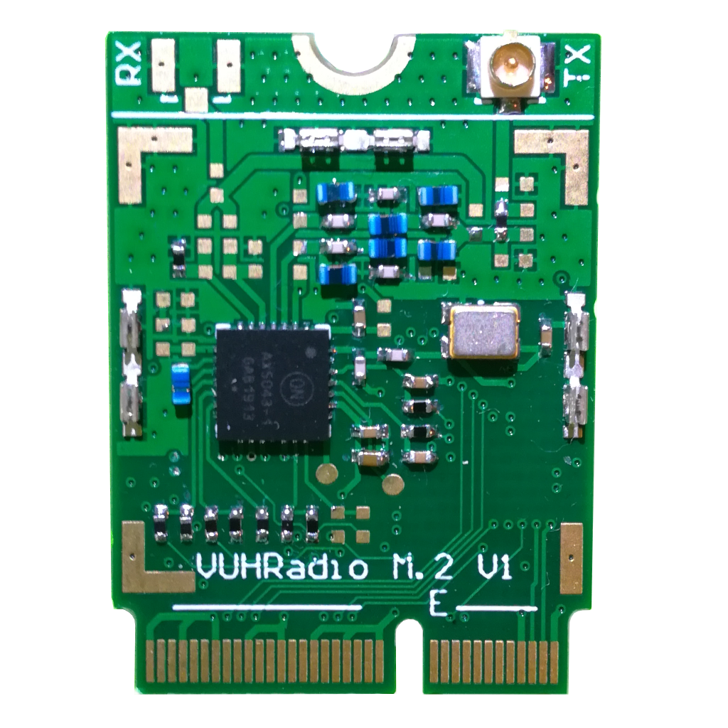
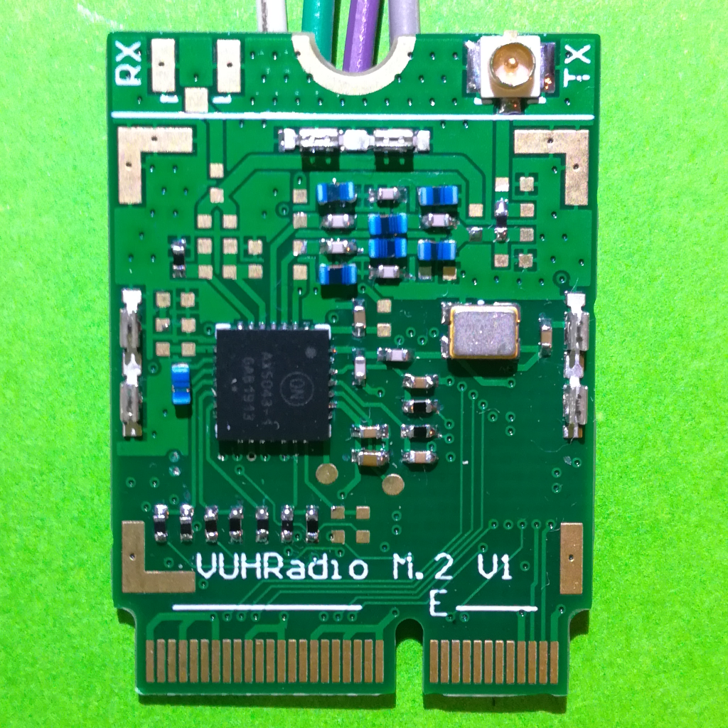
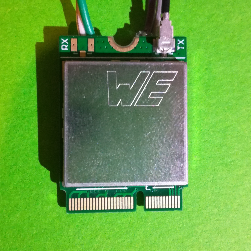
The 3 figures bellow show the assembled PCB from the top, bottom and with a shield on top (from left to right).
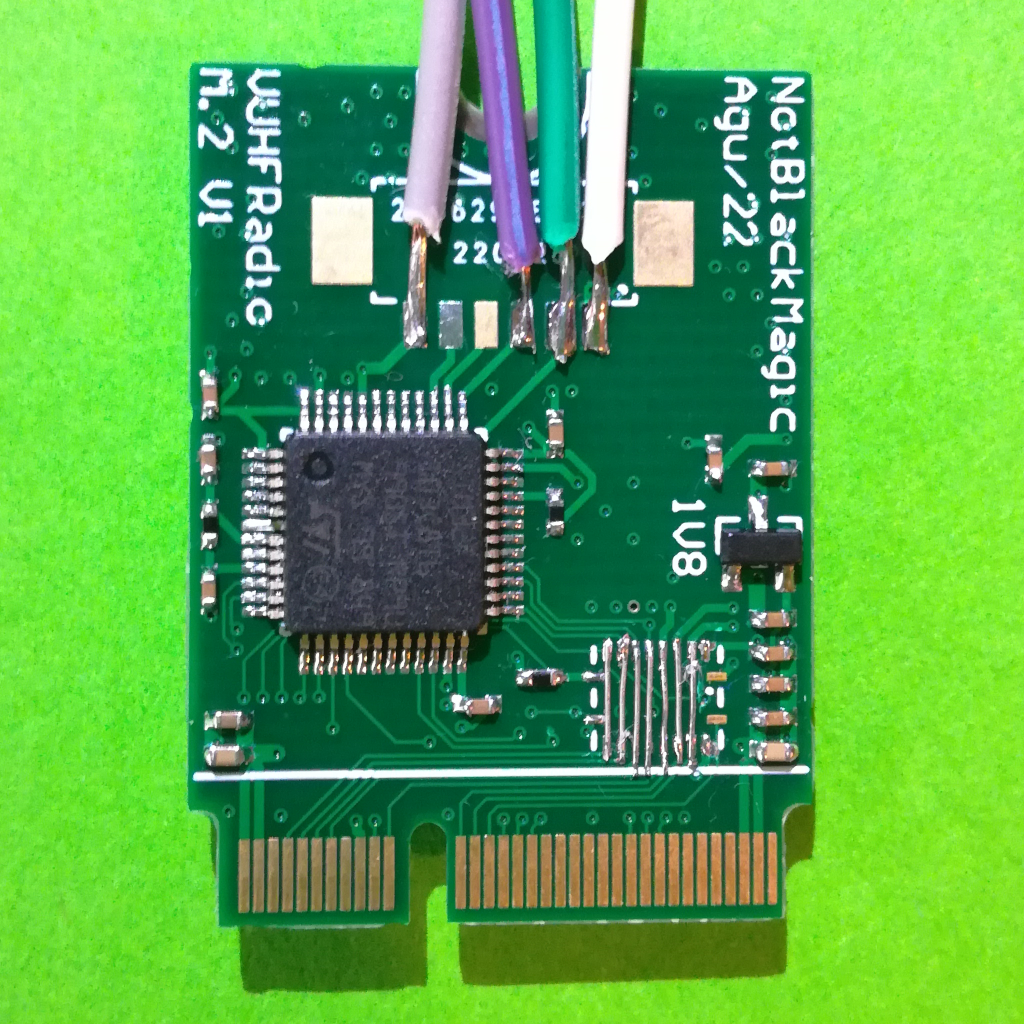
On the top side is the transceiver IC, the AX5043, with the required matching network and the TCXO as well as pads for a 20mmx20mm shield. The bottom side has the MCU (STM32F103C8T6), the level translator (TXS0108E) and the debug interface connector for the MCU. The digital system, MCU and level translator, are located as far away as possible to the RF circuitry, specially the matching network, to reduce interference and keep the transceiver performance as high as possible. Also on the bottom side view of the PCB, the fixes required to mitigate the design errors are visible: The level shifter is not soldered and its pads are bridged; The MCU debug connector is not soldered and soldered on wires are used in its place.
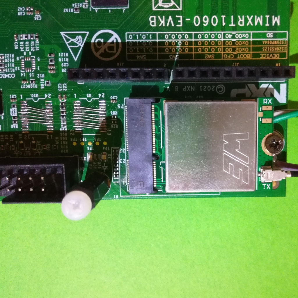
The module was tested with, and fits perfectly in the M.2 slot of the MIMXRT1060-EVKB development board. All interface connections are correctly mapped, including the digital IQ mode pins mapped to the SAI peripheral pins of the development board, adding this way a Sub-GHz radio with digital IQ data access to this development board. The VUHF M.2 module fitted on this development board, in the top left corner, is shown in the figure bellow (on the left the removed and shunted level shifters of the development board can be seen):
M.2 Connector
The VUHF M.2 modules edge connector follows the M.2 Key E standard and pinout, with the pinout used by NXP for their radio modules. This pinout is shown in the figure bellow:
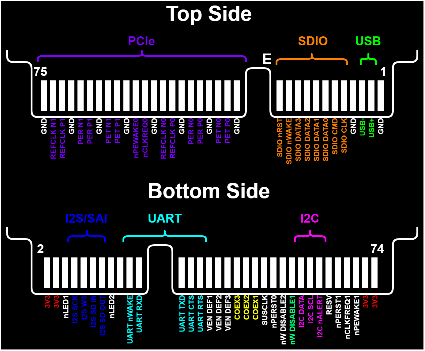
Not all pins are used for this module, and some are used with a different purpose. The used pin (groups) are the following:
- UART: All 5 UART pins are connected to the MCU, but only the RX and TX are in use currently
- I2C: All 3 I2C pins are connected to the MCU, but none are in use currently
- USB: The USB pins are used, with the MCU providing a Virtual COM (VCOM) port over it
- I2S/SAI: This is used to output the AX5043 Digital IQ signal (experimental feature), compatible with SAI TDM with the AX5043 being the master and providing the master clock
- COEX1/2/3: COEX1 and COEX2 are connected to the AX5043 GPADC1 and GPADC2 respectively (also used to output analog IQ) while the COEX3 connects to the DAC output
- nW DISABLE1: Connected to the nRESET pin of the MCU
To follow the M.2 specifications, the UART and I2S/SAI pass through a level shift IC (TXS0108E) which converts from the modules/MCUs 3.3V levels to the M.2 standards 1.8V levels.
The module is directly powered from the four 3.3V power pins, which should be connected to a clean 3.3V power source for optimal performance of the radio. The 1.8V required for the level shifting is generated on the module through a 1.8V LDO. The minimum number of connections required to use the module are 4: one GND, one 3.3V and 2 for either the UART, RX and TX, or USB lines.
Matching Network
The VUHF M.2 module has the footprint for the matching networks of both the full differential mode, as well as for the single ended mode, and for both the AX5043 as well as for the new AX5045. In general, the differential TX PA mode is used, where the RX and TX share the same path reducing the number of components required. The schematic for this matching network, for the AX5043, is shown in the figure bellow, with indication of the different functional areas:
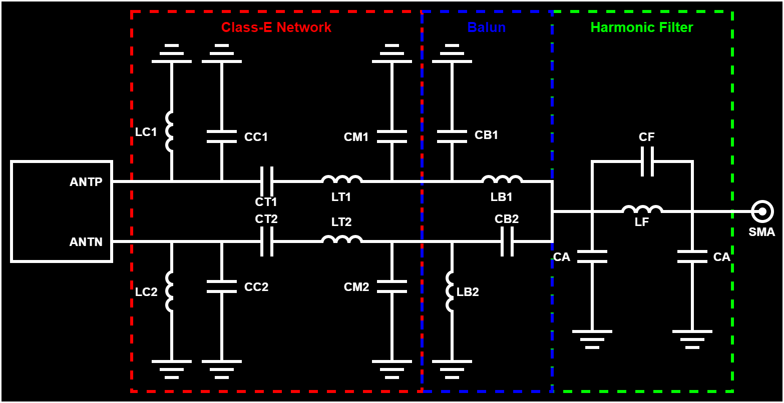
The OnSemi forum has a good post which briefly explains each of these functional areas and how to dimension them for the desired frequency bands. In short there are three functional areas:
-
Class-E Network: The internal PA is a class-E amplifier and therefore requires a load network, which is achieved by the components in this area. A good resource about class-e leading networks is this (from the OnSemi forum).
-
Balun: The balun network is responsible for both converting the differential output of the class-E loading network to a single ended output, which will connect to the harmonics filter and the antenna, as well as acting as a matching network between the two (class-E loading network and harmonic filter). The differential output of the class-E network has around 100 Ohm differential while the harmonics filter, and antenna, are 50 Ohm single ended. There are a few online calculators for the balun components, the one used in the OnSemi forum post is this one.
-
Harmonic Filter (optional): The harmonics filter, responsible for filtering out the harmonics of the carrier frequency, is a 3rd order passive low-pass filter. Different types of filters can be implemented here, but the used component arrangement is specifically designed for an Elliptical filter. Again, there are a few online calculators for the component values of this low-pass filter, with the one used in the OnSemi forum being this on.
For the most used bands, 169 MHz, 433 MHz, 470 MHz and 868/915 MHz, the datasheet of the AX5043 provides recommended values for the components in the matching network, which are also shown/used in the VUHFRadio project, and therefore for those bands none of the above calculators have to be used.
The firmware running on the MCU is the same as for the VUHFRadio project, with required modifications and therefore in its own branch on GitHub (branch: M.2_Module). This means that this module also uses the same communication protocols, the CAT protocol for commands and the KISS protocol for data packets. The CAT protocol used is based on the CAT protocol by HAM Radios from YAESU or Kenwood, under others. The KISS protocol is a very simple and commonly used low level TNC protocol, and for which a short explanation can be found here. Just as the VUHFRadio module, both these protocol run over the same interface and can be used at the same time, with some considerations.
Explanation on how to program/configure the AX5043 transceiver can be read found on its dedicated page.
The full software is available on Github: VUHFRadio
CAT Commands
The CAT protocol used uses ASCII style commands with the following structure: “AFraaaaaa;". The first two ASCII characters indicate the command type, here AF is for “AFC Control” command, followed by a single number, r, to select which radio the command is meant for (only applicable for the VUHFRadio, here use always “0”). This is then followed by the argument(s) for the command, also in ASCII, aaaaaaa, and a command terminator, ;. This structure is for a set/write command, to change a setting. In a get/read command, the argument(s) are omitted e.g. “AF0;".
The full list of available commands can be downloaded bellow (or from the VUHFRadio project):
CAT Commands: VUHF_Radio_CAT_Commands.pdf