This DIY multispectral imaging system was was built to explore low-cost spectral imaging for precision agriculture, with applications like plant health monitoring and weed detection. Originally developed for the AgroWeed Seeker project as part of the AMD Pervasive AI Challenge, the system uses active illumination and a custom-built 8-channel LED driver to capture spectral data using a standard camera.
Most traditional multispectral systems that rely on expensive sensors or filters, see Spectral Imaging page, active illumination uses different light sources to isolate spectral bands, enabling spectral acquisition with an off-the-shelf monochrome global shutter camera, preferably one with strong infrared (IR) sensitivity. Since the light source defines spectral width, purity, and the number of bands, it is the most critical part. Few of-the-shelf solutions exist that fit this application, often being expensive, leading to the development of a dedicated multichannel LED driver board.
To ensure high performance, a linear (constant current) LED driver should be used over the more common pulsed/PWM drivers. Here the ILD8150 was selected for its ability to provide efficient linear drive control via a switched mode controller at a low-cost. Instead of using a multichannel driver, individual drivers were chosen to accommodate LEDs, from IR to UV, with significantly different $V_{FW}$ values (e.g., IR LED with $V_{FW}=1.2\ V$ vs blue LED with $V_{FW}>3\ V$), resulting in widely varying LED driver output voltages, which most multichannel drivers are not designed to handle.
While the 8-channel LED driver board was designed for multispectral imaging, its versatility makes it ideal for DIY lighting panels, research, or photography where independent control of multiple LED channels is valuable. Currently the multichannel LED driver has the following, implemented, features:
- 8 independently controlled LED drivers
- Each channel supports up to 720 mA at 30 V
- Linear (constant current) dimming control down to 12.5 %
- Hybrid control for dimming down to 0 %
- High-speed flash mode down to 4 ms
- Serial interface for simple control
Version History
Revision 1
Schematic: LED_Driver_Baseboard_Schematic_V1.pdf
Gerber: LED_Driver_Baseboard_Gerber_V1.zip
The LED driver baseboard is in the first version.
Schematic: LED_Driver_Schematic_V1.pdf
Gerber: LED_Driver_Gerber_V1.zip
The LED driver daughter board is in the first version.
Overview
The LED driver board is made up of two different PCBs, the baseboard and the LED driver module. This design is similar to many 3D printer controller boards, where the stepper driver boards are separate modules. This way different LED driver can easily be developed and tested, as well as simplifying the PCB layout of either boards specially the routing of the high power supply traces. Additionally this design enabled a more compact overall system, as the LED driver boards are mounted 90 degrees of the board and therefore allowing the tighter packing of them.
The LED driver baseboard can hold and control up to 8 LED driver modules creating a 8 channel LED driver board. The driver boards connect to the baseboard through right angles 2.54mm headers, with 4 pins at the pack caring power and two control signals, enable/shutdown and dimming control, and 2 pins at the front caring the LED drive signals to the cathode and anode. The dimming control is simply a PWM signal that can be filtered to create a DC signal using a simple RC low pass filer. The control of all 8 channels is handled by an STM32G4 MCU, the STM32G431, with diverse set of peripherals routed to JST-GH headers to control the driver board: I2C, UART and CAN.
Below is a view of the LED driver baseboard with the location of the different functional modules:
Power Supply
The power input of the driver baseboard includes two connectors: an XT-30 and a JST-GH 6-Pin header. They are connected to the input power rail each with there own Schottky diode and could therefore be used as a redundant power input. The input power rail is is monitored, both current and voltage, by a power monitoring IC, the IN234, which is connected through I2C to the MCU. The input power rail both provides power to the MCU and its peripherals as well as being the supply for the LED drivers them self. The maximum input voltage is 30V, limited by the used buck converter, and also limits therefore the maximum LED series string that can be powered and controlled i.e., for white LEDS with a forward voltage of up to 5V this limits it to 6 LEDs in series.
The power supply for the LED driver baseboard is very simple, only consisting of a single buck converter to generate a 5V rail and an LDO to generate the 3.3V rail. The buck converter is a 3A buck converter, the TPS62933, with a maximum input voltage of 30V. The LDO for the 3.3V rail is a 1A LDO, the TLV76733, powered from the 5V rail and used to power the MCU, power monitoring IC and EEPROM.
MCU
The control of the LED driver board is handled by an STM32G431 MCU, a ARM Cortex-M4f based MCU running at up to 170 MHz with 128 kBytes of flash and 32 kBytes of SRAM. This MCU is both cheap, new and includes a diverse set of peripherals including FDCAN. It also features a diverse set of analog peripherals (2 12-bit ADCs and 4 12-bit DACs) but these are not used here.
The MCU connects directly to the diverse set of control interface connectors (UART, I2C, Trigger In, Debug) and through a CAN SIC capable transceiver, the TJA1463, to two in parallel connected CAN ports. The control interface to the 8 independent LED driver modules is composed of two IOs, one simple ON/OFF enable/sleep IO and one PWM controlled IO used for dimming control. With the added optional RC filter, the PWM control can be converted to a analog dimming control signal if so desired. Finally, the MCU also connects over I2C to the input power rail monitor IC, the IN234, and a EEPROM, the AT24C01D, for persistent configuration changes.
Interfaces
The LED driver baseboard has seven interface connectors: five control interfaces to control and communicate with the driver board, one debug interface and the LED output channel header. The five control interfaces available are two CAN connectors (shared port), one I2C port, one serial/UART port and one trigger in port. The CAN, I2C and UART port follow the Pixhawk standard, including outputting a 5V power signal. The debug interface also follows the Pixhawk standard, providing a debug serial interface as well as a SWD programming and debugging interface. Finally, the LED output channel header is a two row 2.54mm pin header with the output of each LED driver, each channel, connected to opposing pins: cathode on the inner row and anode on the outer row.
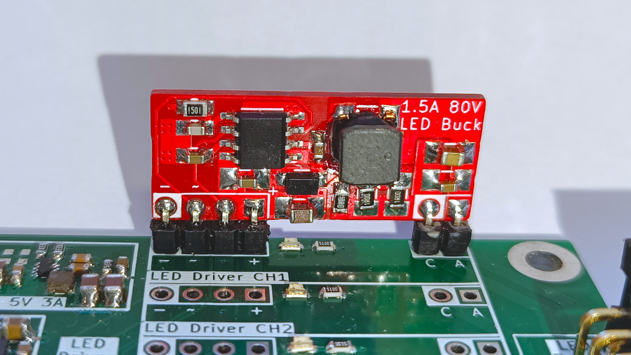
LED Driver Daughter Board
The first, and for now only, LED driver module developed is based around an Infineon DC-DC LED driver, the ILD8150. This DC-DC LED driver has an integrated output FET and can provide up to 1.5A average output current while operating at up to 80V. But the most important feature is its hybrid dimming capability, operating in a analog way down to 12.5% of the set maximum output current and in a high speed (3.4 kHz) hybrid dimming down to 0.5% output current. This enables guaranteed completely flicker free operation between 12.5% to 100% output current range while being able to each a dimming level of 0.5% in a mostly flicker free way.
The dimming is controlled with a PWM signal with a frequency between 250 Hz and 20 kHz, where the duty cycle controls the output current level (dimming). The dimming is proportional to a programmable maximum output current, allowing the tailoring of its analog dimming range to specific applications. The maximum output current is set by the, low side, current sense resistor $ R_{CS} $ connecting the LED cathode to ground, and is given as $ I_{OUT} = 0.36 / R_{CS} $. The use of low side current sensing by this LED driver IC is also the reason why each LED output channel requires two dedicated connections, none of the terminal between the channels can be shared.
Besides $ R_{CS} $, other components that have to be dimensioned is the inductor $L$, the output capacitor $C_{OUT}$ and the feedback loop RC filter components $ R_{flt} $ and $ C_{flt} $ connected to the CS pin. For this driver board, the inductor chosen is a 100 uH 5040 size (5x4 mm) power inductor, the VLS5045EX-101M-H, rated for a continuous current of 800 mA. This selection is mainly based on dimensions and on the reference design from Infineon. The values for the RF filters are also taken from the same reference design and are $ R_{flt} = 1.5\ k\Omega $ and $ C_{flt} = 180\ pF $. Based on this, the switching frequency $f_{SW}$ of the current control switches mode supply can be estimated using the equation below and where $ V_{CSH} = 390\ mV $, $ V_{CSL} = 330\ mV $ and $ t_{delay} = T_{CSSW} + R_{flt}C_{flt} $ ($ t_{CSSW} = 120\ ns $):
$$ f_{SW} = {R_{CS} \over {L(V_{CSH} - V_{CSL}) + R_{CS}V_{IN}t_{delay}}} {{V_{OUT}(V_{IN} - V_{OUT})} \over V_{IN}} $$
As an example, based on result in the Results section, using a $V_{IN} = 20\ V$ and $V_{OUT}=18\ V$, for a series of 6 white LEDs, the switching frequency $f_{SW}$ is around:
$$ f_{SW} = {0.5 \over {100u(0.39 - 0.33) + 0.5\times20\times390n}} {{18(20 - 18)} \over {20}} = 90.9\ kHz $$
Version History
Revision 1
Schematic: Multispectral_Illuminator_Schematic_V1.pdf
Gerber: Multispectral_Illuminator_Gerber_V1.zip
The LED multispectral illuminator is in the first version.
Overview
The LED multispectral illuminator is a simple PCB that holds 8 series of 6 LEDs each (2016 LED size), creating therefore a 8-channel LED illuminator. The PCB is designed to be mounted to a camera module with 28x28mm mounting holes, here this is a OV9732 camera module for preliminary testing purpose. The 6 LEDs of each of the 8-channels are equally spaced around the square PCB therefore creating a mostly uniform illumination of a target for the camera. Due to the design of the LED driver, each channel has its two terminals, anode and cathode, of the string of LED routed to a 2.54mm 2x8 pin header. This header then connects with a ribbon cable to the LED driver baseboards also 2.54mm 2x8 pin header.
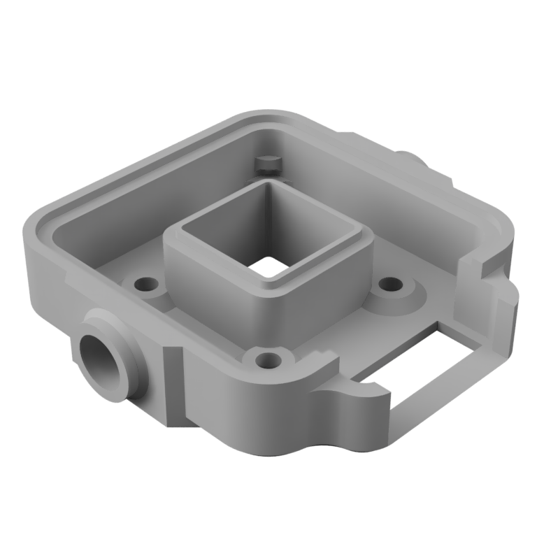
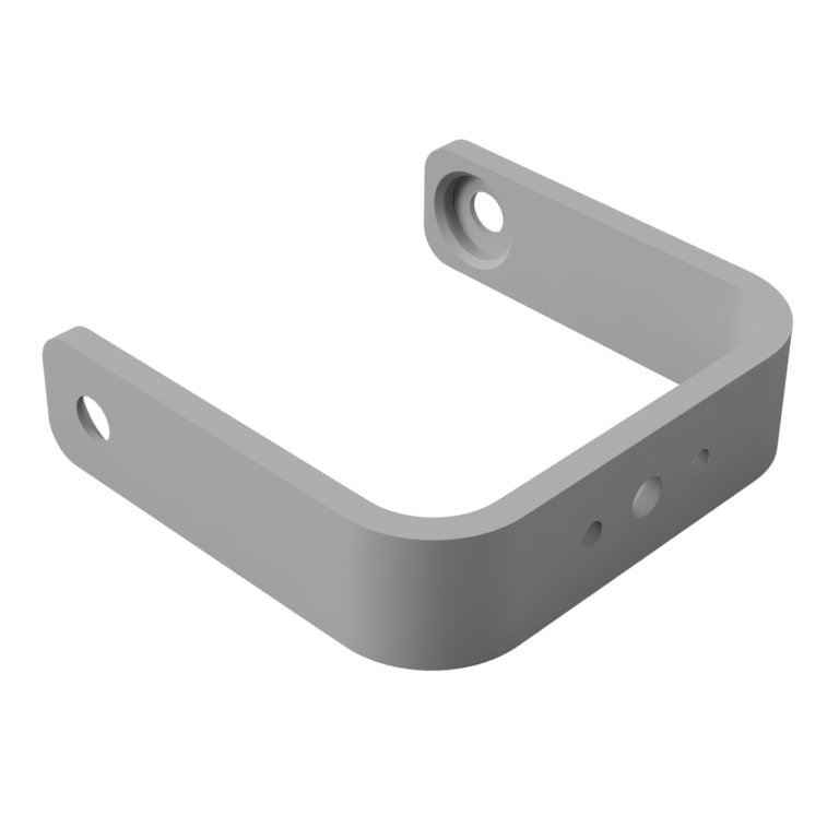
This illuminator is accompanied by a custom housing and tilt holder. The housing has holes at the back for M2.5x4x4 threaded inserts, to where the camera module can be mounted onto. Additionally, the housing has holes on either side for 1/4 inch threaded inserts. This is used to fix the tilt holder and matched the standard 1/4 inch screws used for camera setups. The illuminator PCB itself clips into the housing and is friction hold in place. For improved light output, the insides of the housing can be wrapped with reflective tape.
Below are the .stl files for each of these pieces, ready to be sliced and printed on a 3D printer.
Multispectral Version
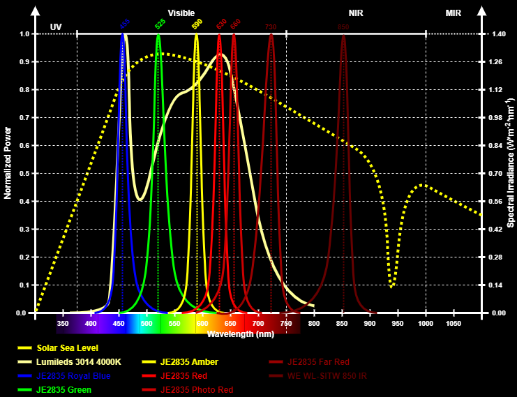
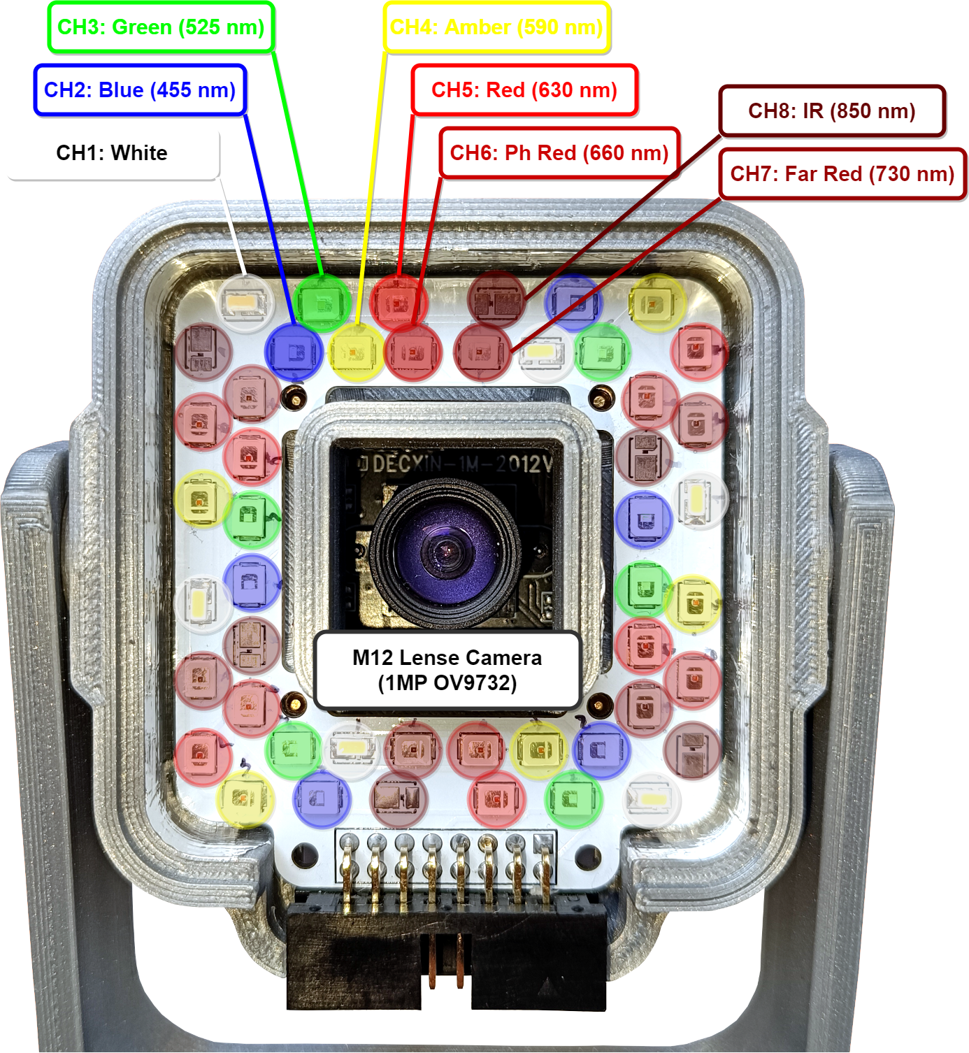
The LED multispectral illuminator can be populated with a different combination of LED colors/bands, depending on the target application. For testing purpose, with a crop health monitoring application in mind, the illuminator was populated with a 4000K white LED, a blue LED, a green LED, a amber/yellow LED, three different red LED and a near IR 850nm LED. The higher density of bands in the red to IR region is because in crop health monitoring this is the region of most interest. Below is a graph showing the different LEDs installed with there respective approximate spectral bands:
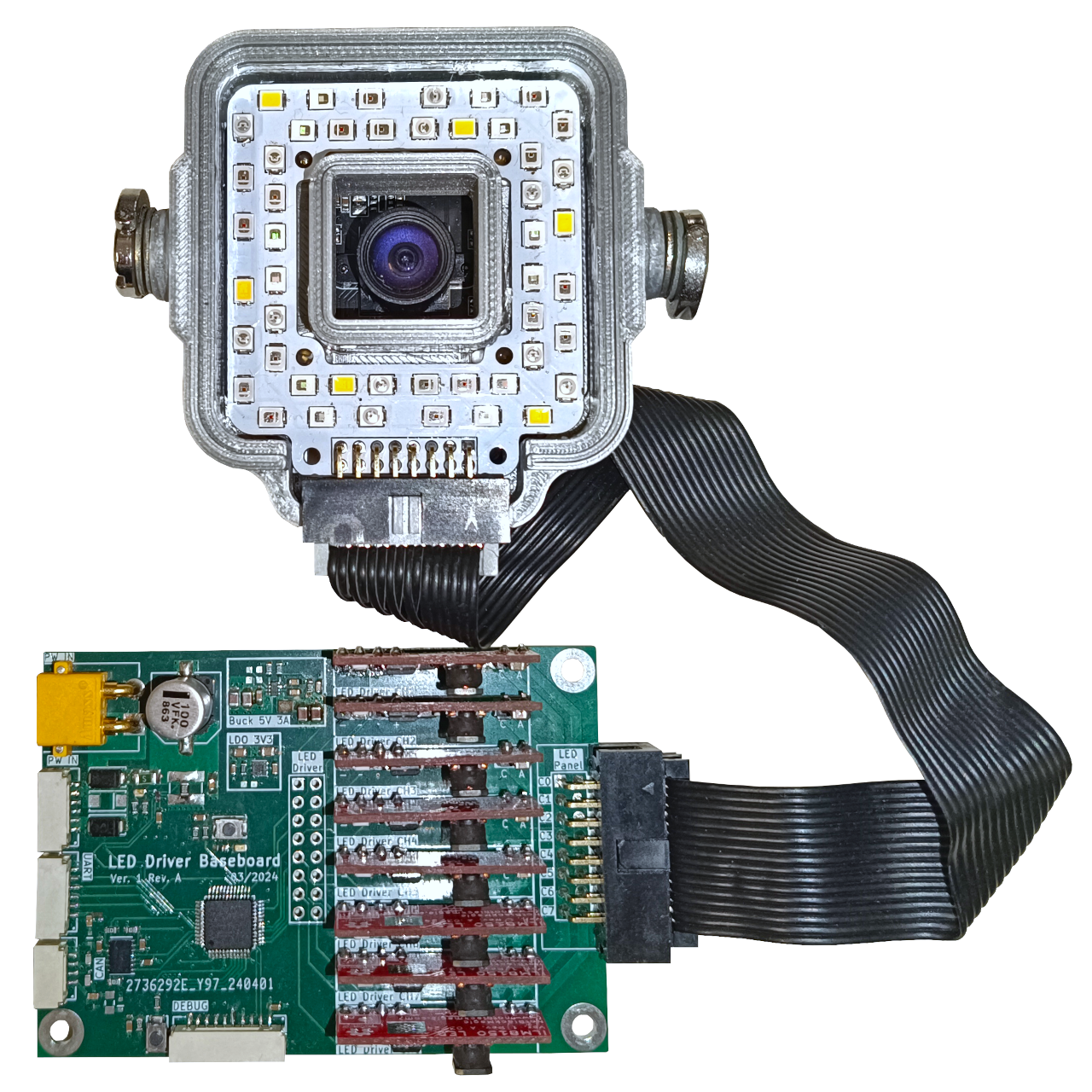
The fully assembled LED multispectral illuminator, with the different LEDs, inside its 3D printer housing and with the camera module mounted is shown in the picture below.
The firmware for the LED driver board is quite simple, reading/measuring power consumption through the IN234 over I2C and controlling the 8 individual LED driver daughterboards through a PWM and IO signal. The LED driver board can be controlled over different digital interfaces: serial (UART), I2C or CAN.
The full firmware is available on Github: MultichannelLEDDriver
Besides the firmware for the LED driver board, a simple Python “driver” was developed for controlling the LED driver board from a SBC, such as the NavQPlus or KR260, over serial. This code can also be downloaded: DriverIlluminator.py
Interface
This section explains how each of the available interfaces, UART, I2C and CAN, are intended to be used and how to interface with them. The CAN and I2C interface are not yet implemented.
Serial (UART) Commands
The UART interface uses the standard 8-N-1 format and a baudrate of 115200. A small set of commands and feedback values are currently implemented. They all follow a simple ASCII format, for commands this is: “CMD:ARG0;ARG0;ARG0;” for controlling multiple channels (from channel 1 to N), or “CMDx:ARG;” for controlling a single channel “x”. Below is a short list of the available commands and their respective function:
Basic Configurations
- Enable/Disable Channel (“ENx:ARG;"): Enables, or disables, a single or multiple channels output. E.g. enable channel 3: “EN3:1;”, set multiple channels (1 to 4): “EN:0;1;1;0;” (Enable channel 2 and 3, disable channel 1 and 4).
- Set Channel Current (“CURx:ARG;"): Sets a single or multiple channels drive current value in mA. E.g. set channel 5 drive current to 160mA: “CUR5:160;”, set all channels to 200mA: “CUR:200;200;200;200;200;200;200;200;”
Flash Configurations
- Set Flash Mode (“FMD:ARG;"): Sets the driver flash mode: 0: Off; 1: Single Channel; 2: Sequential Channels; 3: All Channels. E.g. set to single channel flash mode: “FMD:1;”
- Set Flash Channel (“FCH:ARG;") Sets the flash channel for single channel flash mode, or start channel in sequential mode. E.g. set to channel 3: “FCH:2;”
- Set Flash Channel Current (“FCRx:Arg;"): Sets a single or multiple channels flash drive current value in mA. E.g. set channel 2 drive current to 75mA: “FCR2:75;”, set all channels to 20mA: “FCR:20;20;20;20;20;20;20;20;”
- Set Flash duration (“FDR:Arg;"): Sets the flash duration, LED ON period, in ms. If set to 0 follows the flash trigger signal, i.e. LED stays ON while flash trigger signal is active. E.g. set to 15ms: “FCR:15;”
- Set Flash delay (“FDL:Arg;"): Sets the flash delay, time between trigger signal and LED ON, in ms. E.g. set to 5ms; “FDL:5;” (with delay set to 0, the real delay will be at least 1.8ms due to hardware).
Advanced Configurations
- Set PWM Frequency (“FRQ:ARG;"): Sets the driver control PWM signal frequency, in Hz, for all channels. E.g. set to 10kHz: “FRQ:10000;”
- Set Channel PWM Duty Cycle (“PWMx:ARG;"): Sets a single or multiple channels driver control PWM signal duty cycle (from 1 to 1024). The duty cycle corresponds to the fraction of the maximum drive current to be used (from 1/1024 to 1024/1024). For output drive current control in mA use the Set Channel Current command. E.g. set channel 1 PWM duty cycle to 45%: “PWM1:461;”, set multiple channels to 10% duty cycle (1 and 2): “PWM:102;102;”
The LED driver board also outputs periodically, every 1s, the power consumption of the whole board in the format “PWR:%d;%d;%d;\n”, where the first value is the supply voltage in mV, the second the supply current in mA, and the last the power in mW. Values are measured by the IN234.
I2C
Not implemented yet.
CAN
Not implemented yet.
The LED driver configuration used throughout the results section is with a $ R_{CS} = 0.5\ \Omega $, made up of two parallel $1\ \Omega$ 2010 SMD resistors. This results in a maximum output drive current of $ I_{OUT} = 0.36 / 0.5 = 720\ mA $. The first test with this configuration is to evaluate the LED driver output ripple for different output capacitors $C_{OUT}$ which is connected across the LED driver outputs anode and cathode. This test was performed with the LED driver connected to the LED multispectral illuminator, specifically to channel 2 which contains 6 series blue LEDs, the CREE JE2835 Royal Blue. These LEDs have a typical forward voltage of $V_{FW}=2.96\ V$ according to the datasheet, giving a total forward voltage of around 18 V and therefore the board was powered with a 20 V supply. For a worst case scenario, and to observe the hybrid control regime of the ILD8150 LED driver, the output current was set to $I_{OUT} = 50\ mA$ by providing a PWM signal with a duty cycle of 7 % to the LED driver control input. Three different $C_{OUT}$ values where then used and tested, 10 nF, 100 nF and 10 uF. The result of this experiment is shown in the graph below.
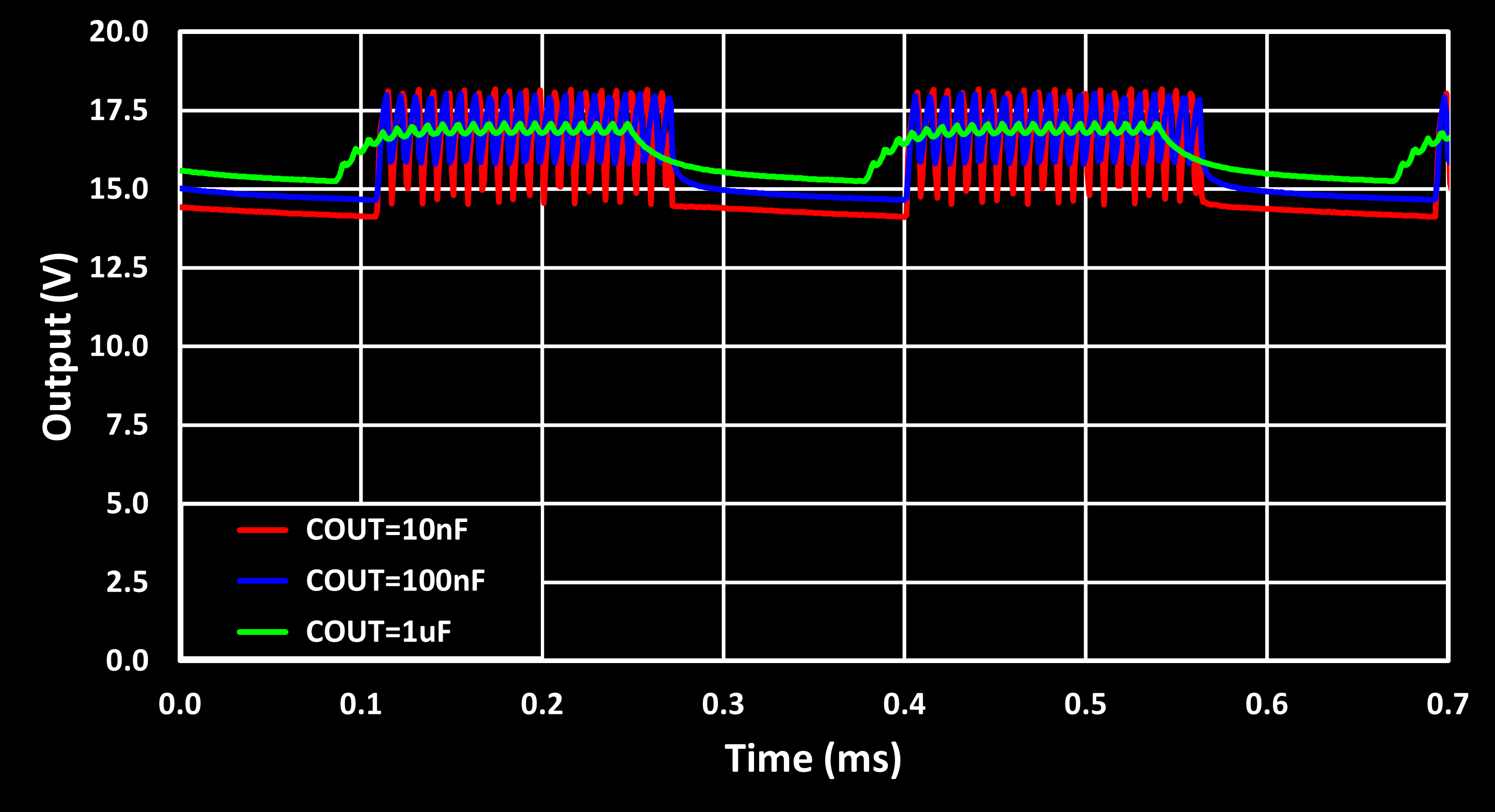
This graphs shows well the hybrid control of the ILD8150 LED driver, used for output current below 12.5 % of the maximum (i.e. here below 90 mA). The hybrid mode duty cycles the constant current mode which in turn is achieved by a switched mode power supply scheme, a buck converter. This results in a low frequency PWM signal, of 3.4 kHz, enabling and disabling the high frequency switching power supply, with itself a switching frequency of ~130 kHz for the used test conditions (see the LED Driver Daughter Board section).
It is important to note here that the output voltage never reaches 0 V this is because when the output voltage, on the off cycle of the PWM signal, drops below the voltage required to drive the LEDs, the current is basically 0 mA, only a small leakage current remains. This results show that a $C_{OUT}$ of at least 1 uF is recommended to get a ripple voltage of under 500 mV, with the 1 uF option giving a good enough result while keeping costs for the capacitor low (small form factor and high voltage tolerance equals high cost…) and its therefore the capacitor value used here.
The next experiment is to evaluates the LED driver’s ON delay, the time between enabling the LED driver via the Shutdown (SD) pin and reaching a stable output voltage (or current). The results of this test, under the same conditions as before i.e., driving the blue LEDs with 50 mA, are shown in the figure below.
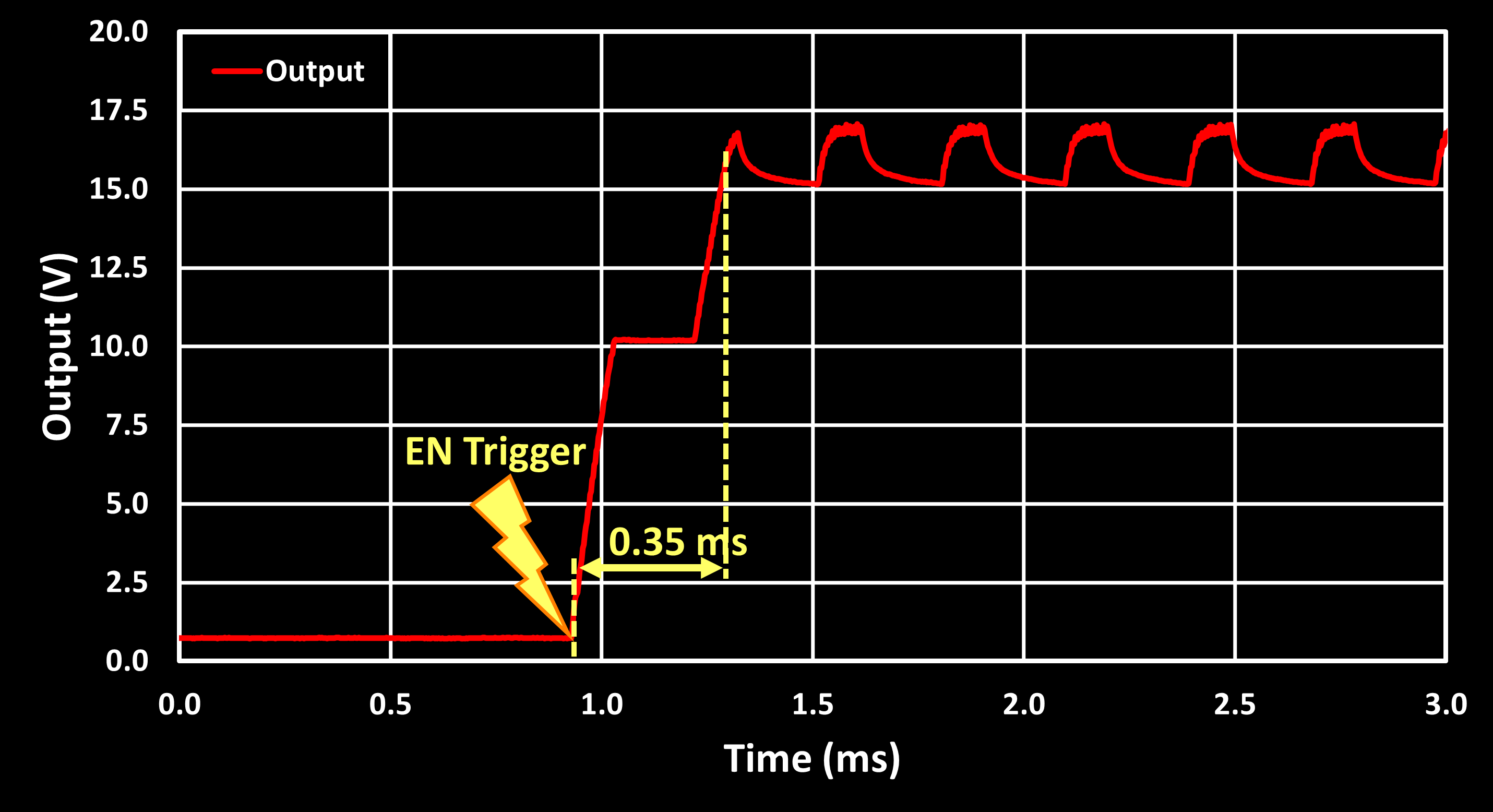
The figure shows an ON delay of around 350 us, after which the LED driver engages hybrid drive mode. This indicates that the system is capable of flash operation, potentially supporting high-speed sync with cameras, as typical sync limits (e.g., 1/250s) allow for flash durations up to 4 ms.
Flash Operation
To enable flash operation, the baseboard includes an external trigger input. The full flash mode was tested by connecting the baseboards external trigger input to a pulse generator. In the first test mode, the LED remains ON for the entire external trigger’s high pulse. The image below shows a 10 Hz pulse (5% duty cycle), where the green trace is the trigger signal and the red trace is the LED driver’s output voltage.
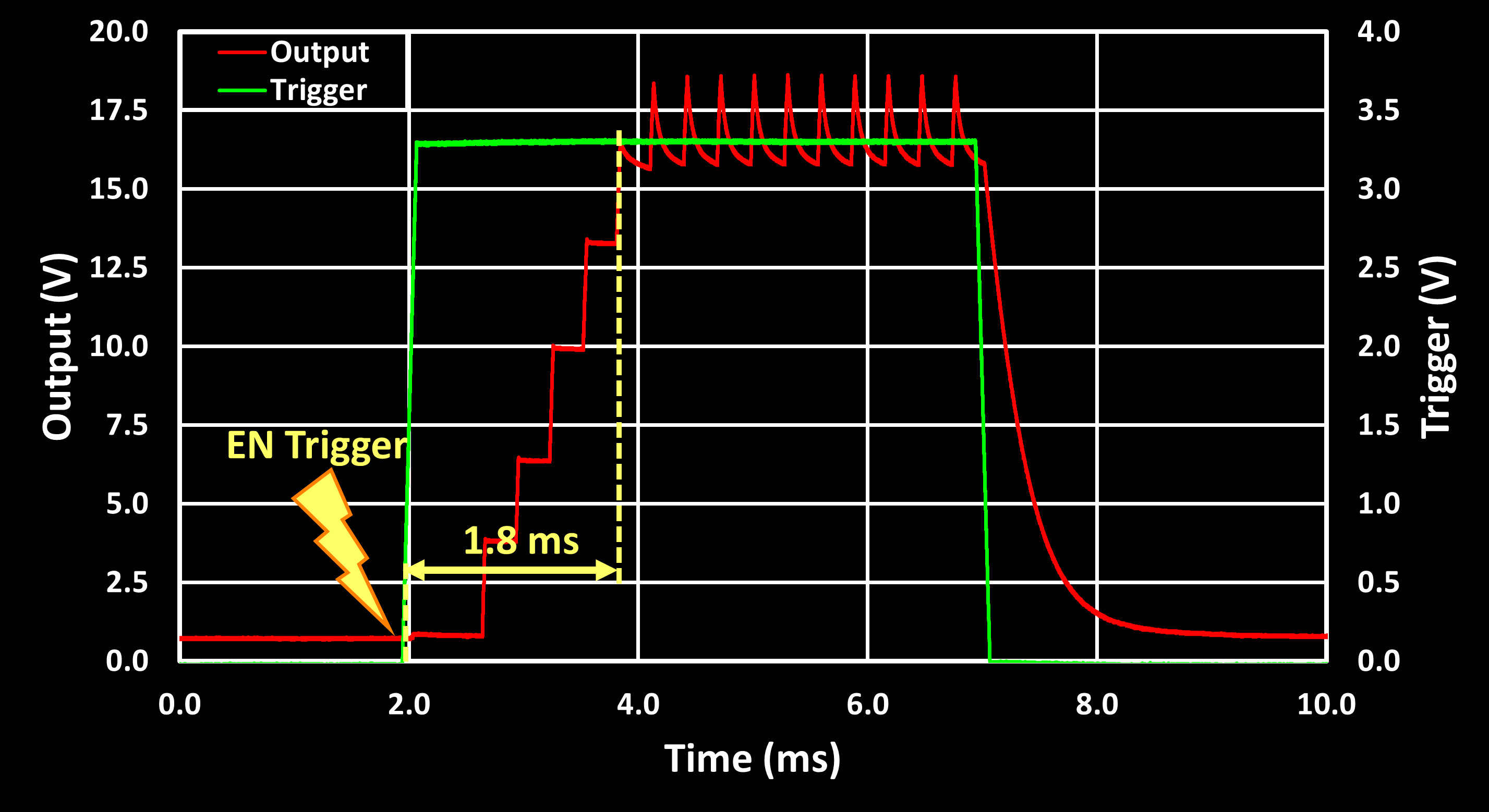
This test revealed an additional ~1.8ms delay from trigger to full output voltage, not seen in the previous test. This delay is influenced by the PWM control frequency, tested here at 10 kHz. At lower PWM frequencies (e.g., 1 kHz), the delay increases as expected. Despite this latency, the system successfully supports flashes as short as 5 ms (1.8 ms delay + 3.2 ms active time), which is within the range of many photographic applications.
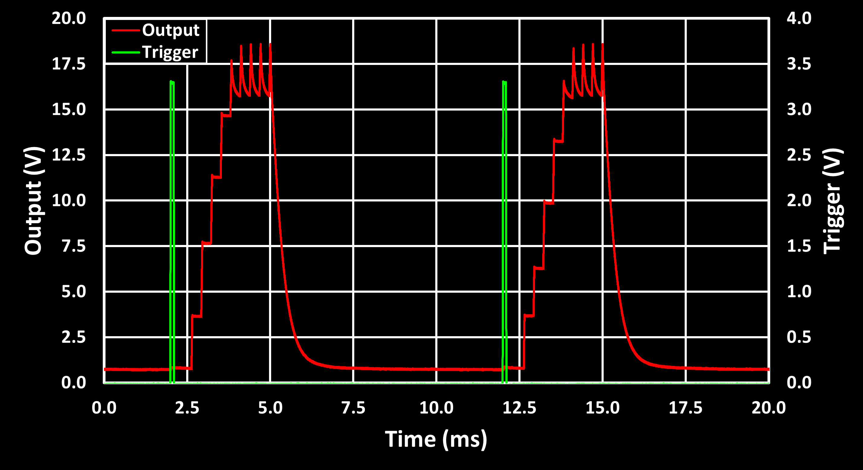
For a second test, the external trigger simply initiates the flash, while the LED driver generates a pulse with a programmable duration. The test below used a 3 ms flash duration triggered by a 100 Hz signal with a ~0.2 ms wide pulse.
Multispectral Imaging Examples
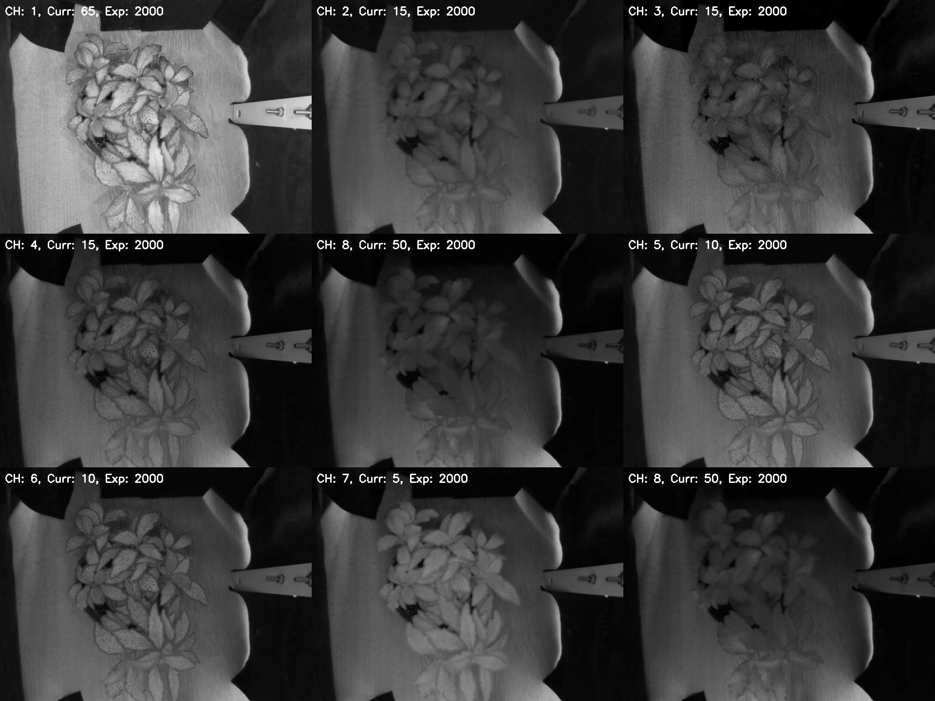
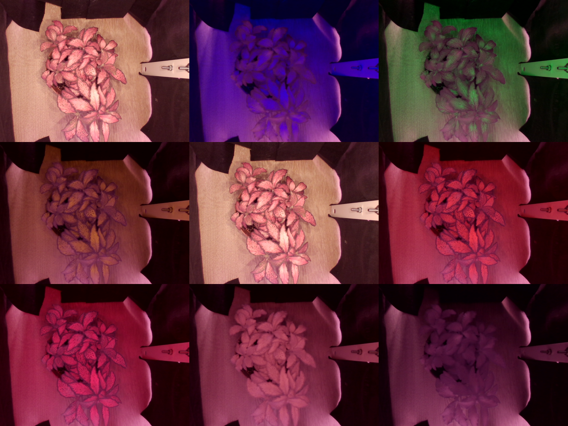
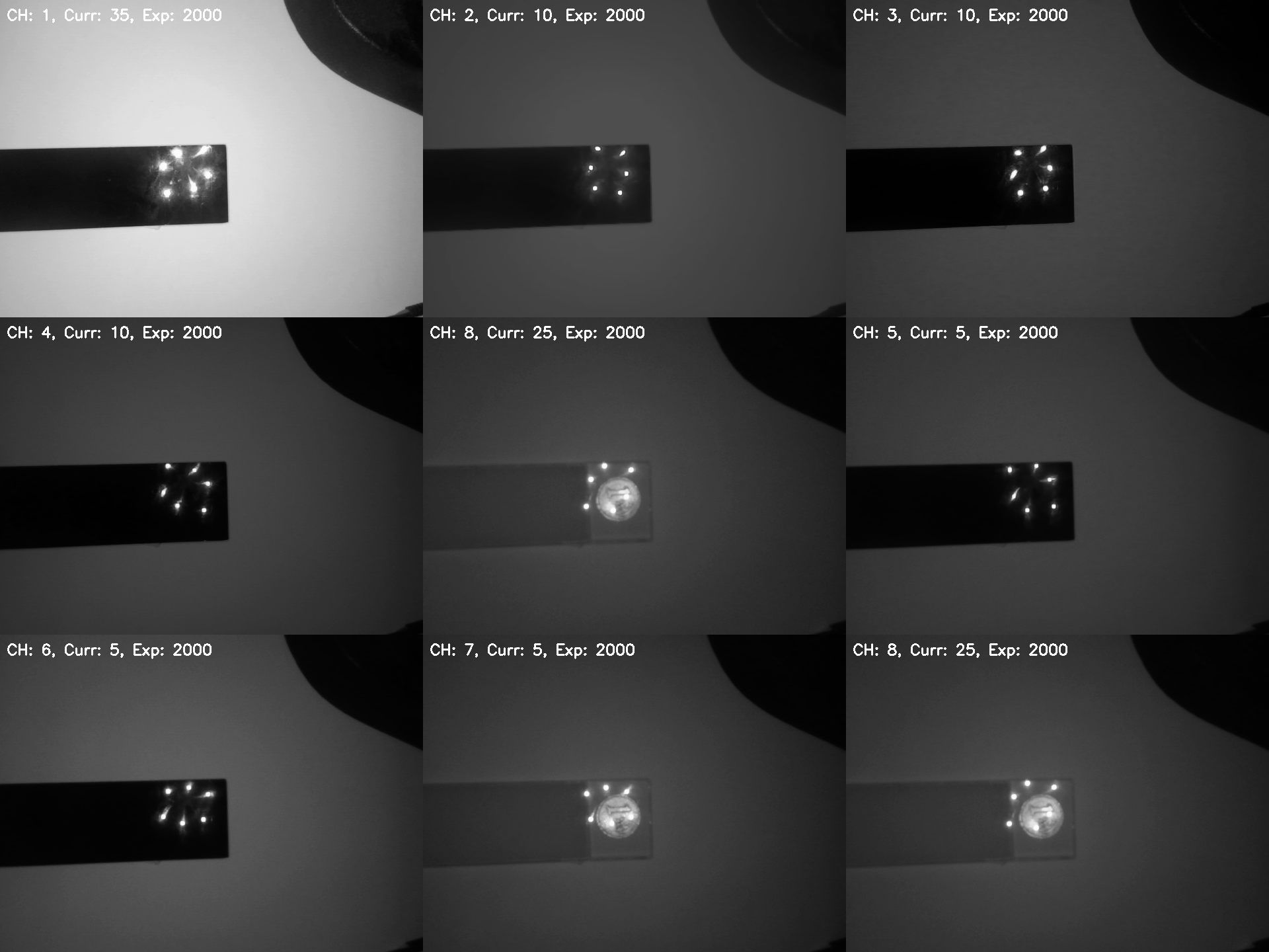
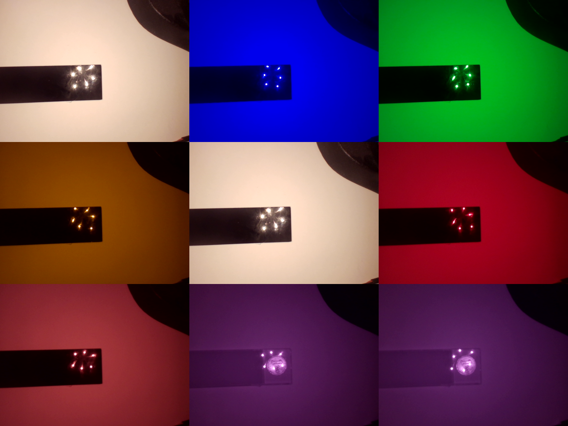
This section contains some multispectral imaging examples taken using the LED driver with the shown multispectral LED illuminator and a cheap USB camera module with the OV9732 sensor. These images were taken as part of the AMD Pervasive AI competition, for my AgroWeed Seeker (AWS) project. The multispectral acquisition is performed one band at a time, with the sample in a enclosure to minimize ambient light and illuminated by a single LED band/channel with the illuminator. This results in a set of 8 images, one per channel/band, as an RGB image as the OV9732 sensor is RGB with the Bayer filter. This is quite useless here and therefore the RGB image is converted to black and white. The 8 images are then stitched together into a mosaic of 3x3 where the center image is a copy of channel 1 image, with the white LED.
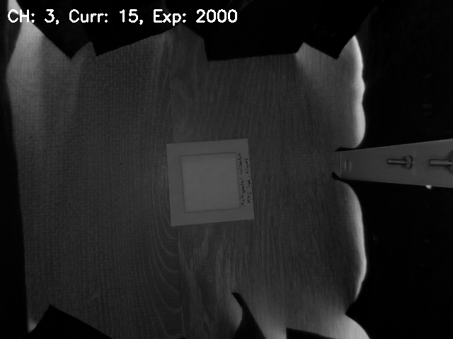
The first step was to calibrate the acquisition setup. This was performed with a PTFE calibration target as PTFE has a near flat response to light from UV to IR. For each channel/band, the light intensity was increased until a averaged BW pixel value, of the pixels covering the PTFE target, of ~75 was achieved. The value 75 originates from how the BW image is obtained, as the average of the R, G and B channels, which each consist of a 8-bit word. This means, if all three channels are excited to the maximum, e.g. with a pure white light, the BW image pixels will have a value of 255. But because here we are using narrow bands of light, often only a single channel, only R or G or B, are excite resulting in a saturation value of 255/3 = 85, so 75 was chosen to give a margin to the saturation. Below is an example image of this calibration for band 3 (green).
After the calibration, the actual multispectral imaging was tested. The first example image set is of a black acrylic strip, with a coin below it. This showcases the transparency of black acrylic to IR light, making the coin visible when using far red and IR light. This is the same material used in covers for IR remotes and receivers.
The second example image set is of a plant, which shows some interesting intensity changes going from red to far red to IR.